
User Manual

HOBO 4-Channel Analog Data Logger (UX120-006M) Manual
4
8. Configure additional sensors. Repeat steps 3 through 7 to
configure up to three more sensors.
9. Select the Logging Interval. Select a logging interval from 1
second to a maximum of 18 hours, 12 minutes, and 15
seconds.
10. Select the Logging Mode:
• Normal. In Normal mode, data will always be recorded at
the regular logging interval set in the previous step. This
is the default setting.
• Burst. In Burst mode, logging will occur at a different
interval when a specified condition is met. See Burst
Logging for more information.
• Statistics. In Statistics mode, maximum, minimum,
average, and standard deviation statistics are calculated
for the temperature during logging, sampling at an
interval you specify. See Statistics for more information.
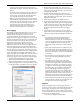
11. Choose when to start logging:
• Now. Loggin
g begins immediatel
y.
• At Interval.
Logging will be
gin at the next even interval as
determined by the selected logging interval.
• On Date/Time. Logging will begin at a date and time you
specify.
• Push Button. Logging will begin once you press the
Start/Stop logging button for 3 seconds.
12. Choose when to stop logging:
• When Memory Fills. Logging will end once the logger
memory is full.
• Never (Wrapping). The logger will continue recording
data indefinitely, with newest data overwriting the
oldest.
• Push Button. Logging will end once you press the
Start/Stop logging button for 3 seconds. Note that if you
also choose Push Button to start logging, then you will
not be able to stop logging until 30 seconds after logging
begins.
If you select the Push Button setting, then you also have
the option to select “Resume logging on next button
push.” This allows you to stop and then restart logging
during the deployment by pushing the Start/Stop button
on the logger for 3 seconds.
Important: When “Resume logging on next button push”
is selected and you use the Start/Stop button to stop and
restart logging, logging will restart on the next even
logging interval, not at the time the button was pushed.
For example, a logger started logging at 7:00 AM with a
logging interval set to 1 hour. If you press the Start/Stop
button to stop the logger at 8:45 AM and then press the
button again at 10:15 AM, logging will not begin
immediately at 10:15. Instead, logging will begin again at
11:00 AM, which is the next even interval time based on
your 1-hour logging interval. Therefore, depending on the
logging interval, the gap between the time you press the
button to resume logging and the time actual logging
begins could be significant. The faster the logging
interval, the less time will elapse before logging resumes.
• Specific Stop Time. Logging will end at a date and time
you specify. Note that if you also configure the logger for
a Push Button stop and to “Resume logging on next
button push,” then the logger will stop logging at the
date you select regardless of how many times you stop
and restart the logger with the Start/Stop button.
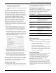
13. Choose whether to keep the LCD on or off. By default, the
LCD will always remain on while logging. If you select the
“Turn LCD off” checkbox, the LCD will not show the current
readings, status, or other information while the logger is
logging. You will, however, be able to temporarily turn the
LCD screen on by pressing the Start/Stop button for 1
second if you select this option.
14. Click the Start button to launch the logger. Note that the
Start button text changes based on the Start Logging
selection. Disconnect the logger from the computer and
deploy it using the mounting materials (see Mounting the
Logger). After logging begins, you can read out the logger at
any time (see Reading Out the Logger for details).
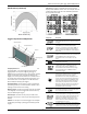
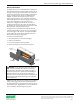
Connecting External Sensors
The logger can accept up to four external sensors (refer to
onsetcomp.com for a current list of supported sensors). Plug
each sensor into one of the four input jacks, making sure each
sensor is firmly seated in the appropriate numbered jack based
on how you configured that corresponding channel in the
Launch Logger window. For example, if you selected “TMCx-
HD” for sensor 1 in the Launch Logger window, then you must
plug the TMCx-HD temperature sensor into the port labeled “1”
on the logger otherwise the logger will not record the correct
data. Connect each sensor before logging begins. Refer to the
sensor or cable manual for more information on connecting the
sensor and wiring, if applicable.
If you disconnect a sensor or if it is not fully inserted into the
jack while the logger is logging, an erroneous sensor reading
can appear on the LCD for that channel. In addition, erroneous
readings will be logged and saved in the data file depending on
the logging interval (e.g. if a sensor is disconnected for 5
minutes and the logging interval is set to 1 minute, then there
will be 5 erroneous data points while the sensor was
disconnected). If you reconnect the sensor, the correct values
will display on the LCD again and will be logged and saved in
the data file.
Some sensors, such as temperature sensors, can be connected
directly to the external input jacks, but others require
additional cables as described in the following sections.
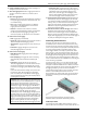
4-20mA Input Cable
The 4-20mA input cable (CABLE-4-20mA) measures current
from 0 to 20.1 mA. Do not expose to current above 20 mA or to