~ "$'' "; ~~ " , ~', ~"A @"ii9\'I:,l~ "I:\;;;i\\'", ~:.- ~ @ " @ " e>. @' ,', @'~;i, ~:.iA ~ ' l' I: ~: . ,\1:\:,A ~ @ ' ~:~- ~ ~",'a @~, ~.~':I.._~ @~ ~ ~:~- ~ " @ ~ ,' ; ,\ l, .' ~~::- 1f . 'i*' .,' ' 1A " z .'... ~ ~ ~~:.-~A"~~ " ~.:rt:::-~ ,.~:- ~:.- ~ , ...~:- 04.~=- ~.~:- ~ ~~ ," " I' ~ . , $ ~:.1W (!:""$ !IIfI z' ~ ~ @ ,\~' ~.~/ ,;I:\;;~A\,,'a ~ i \\' ~::_.' i ~:~... ~~:.- ~~:- ~ \ ...~=-~~~:~, .0 ,~¥ .
TABLE OF CONTENTS Page Parts Layout. . . . . . . . . . . . . . . . . . . . . . . . . . . . . . . . . . . . . . . . . . . . . . . . . . . . . . . . . . . . . . . . . . . . . . . . . . . . . . . 2 Knots to Use 2 FramingtheHulls 4 Trampoline. . . . . . . . . . . . . . . . . . . . . . . . . . . . . . . . . . . . . . . . . . . . . . . . . . . . . . . . . . . . . . . . . . . . . . . . . . . . . . . . 5 Rudder&TilierSystem : 7 Mast & Rigging. . . . . . . . . . . . . . . . . . . . . . . . . . . . . . . . . . . . .
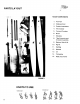
PARTS LAYOUT MAJOR COMPONENTS 6 ;, FIGURE 1. Port Hull 2. Starboard Hull 3. Rudder Assemblies 4. Aft Crossbar 5. Forward Crossbar 6. Boom 7. Sidebars 8. Tiller Extension and Crossbar Assembly 9. Battens: Main & Jib 1 O. Rig Kit 11. Sail Bag 12. Mainsail 13. Jib 14. Trampoline 15. Mast (not shown) 1 KNOTS TO USE ~..~q" FIGURE 8 KNOT 2 BOWLINE KNOT .\\.
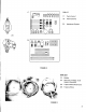
I 17. RIG KIT - CrJ1~~~~~~~ 18. 17. :::::~::::=::::5 ~ ~ ~ ~ . -@UU @ PartsCard # 1 Parts Card #2 @ ~~ @ 20. MainsheetSystem -@oa -@ ~~g,O~ 20. 18 . tt~~~~~ ><= ><= ><= 10 01 10 01 FIGURE 2 WIRE SET I' f 23. " , 24. Jr'" ~\;;;."." J; ;;;; ."; I '~c 1~;;: ; :;x \~fuc:, c. Halyard Assembly ; ,c, cfuci"cc fu~ x c;c,," Bridles Shrouds, Forestay, & Jib '\?cl:i~ ': 25. Trapeze Wire Shock Cord 26. Trapeze Wires , ;;.
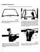
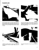
FRAMING THE HULLS Tools needed:Rubber mallet, adjustable crescent wrench, screwdriver, and pliers. FIGURE 4 FIGURE 5 Assemble the frame components as shown in the photo. The flared portion of the sidebar track must be forward and facing inward. With an assistant, position the hulls as shown, using the packing carton end caps for assembly stands. Make sure that the flatter sides of the hulls face outward.
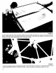
TRAMPOLINE FIGURE8 FIGURE9 Insert trampoline half into the flared sidebar track so that the grommets are running down the center and across the back. The hiking straps should be on top. Position the forward edge even with the forward crossbar. Insert the forward edge of the trampoline into the front crossbar track adjacent to the corner casting and slide it all the way to the center. Repeat steps 8 and 9 for the opposite side.
~~ ./~ . c , ~:C",~;i!;";i!;;~~;i!;CC", ,~-~~,...,.' . FIGURE 12 Tie the center lacing line to the forward grommet on the port (left) trampoline half. Lace the line back and forth, taking up slack as you go. Temporarily tie off the line at the aft end, then remove slack again by working it out front to back. Lace the two aft lines simultaneously in the same manner. "'"' J. FIGURE 13 Once the trampoline is laced as tightly as possible, re-tie all the lines as in Figure 13.
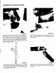
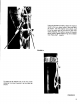
RUDDER & TILLER SYSTEM . i r ., ~@ ii";,,,," ,,~ "~~ FIGURE14 Installthe left rudder assemblyonto the transomof the left hull. The nylon nuts will be facing inboard. With the tiller arm held out of the way, slip the rudder pin - cotter key up - down throughthe castingand gudgeons.Once in place, installthe other cotter key into the rudder pin below the casting (see Fig. 15). Repeatwith right rudder. FIGURE15 Install the drain plugs into their housings in each transom.
MAST & RIGGING , Attach the bridle wires to the bow tangs by removing the bolts and slipping one end of each bridle into its tang. Retighten the bolts. FIGURE 19 Attach the opposite ends of the bridles to the shackle on the bottom of the forestay adjuster. The forestay and shrouds are connected by a large shackle. Attach this shackle to the lower hole in the mast tang, insuring that the forestay is between the two shrouds.
Using the shackle provided, attach the trapeze wires to the two upper holes in the mast tang as shown. Use the trapeze wire shock cord to tie the lower end of the wires to the mast during stepping. For sailing in areas of frequent strong winds, double trapeze rigs are available tram Hobie Ca~ dealers FIGURE 21 ! I To keep the jib halyard out of the way while stepping the mast, secure it at the cleat as shown.
STEPPING THE MAST ""'11 Y, \ ".," ~ L_~~~::~J DANGER!! POWER LINES Do not attempt to step the mast in an area of overhead wires. A mast contacting an electrical wire could be fatal. Lay the mast on top of the frame with the mast head aft. Notes: (a) With experience, the mast can be stepped by one person, but Hobie Cat recommends that you have someone assist you; (b) Position the boat facing into the wind, and on level ground.
I I '. FIGURE Attach the shr.oud stay a.dju~ters FIGURE 24 to th~ anchor bolts Piace the ~~~~ i~~ 25 m~st. pivot bearing in the mast step cup. trallerlng, remove the bearing to prevent on each hull with the clevIs pins & lock rings provided. For initial assembly, attach the shrouds to the top holes of the adjusters, then reset as necessary to remove slack. CAUTION: are not crossed at the dismasting could Make sure that the shrouds mast tang. Shroud failure and result.
CHECK FOR WIRES OVERHEAD. . . . . . Check above at this time for overhead wires. Don't raise the mast if there are any wires. . Stand on the rear crossbar and raise the mast to your shoulder. At this point, insure that the shrouds are clear of the rudders and rear corner castings. An assistant is recommended. FIGURE 28 { ,'.\ \ l -1- FIGURE 29 Walk forward, raising the mast as you go. At the full upright position, lean the mast forward against the shrouds and have an assistant attach the forestay.
Once the forestay is connected, must be disengaged. the mast step link TRAPEZE WIRES , FIGURE 30 FIGURE 31 Assemble the trapeze adjustment components as shown in the illustration. The shock cord should pass beneath the trampoline frame from the port trapeze line to the starboard line. Note: Insure that these items are assembled exactly as above. Refer to knot diagram, "Bowline Knot," on page 2. FIGURE 32 Trapeze assembly installed.
MAINSAIL FIGURE 33 Feed ol:>ening the foot (base) in the forward of end the mainsail of the into the track boom. FIGURE 34 Attach the mainsail tack to the gooseneck shackle as shown. " FIGURE 35 FIGURE 36 Tie the outhaul to the mainsail clew with a bowline knot. Lead it around the boom cal:>,through the block hangers, and through the outhaul jam cleat. Tie a figure eight knot in the end of the line.
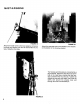
DIAGRAM - TYING DE:TAIL CLE:AT OF"F" AT MOUT1-i OF" LE:ACH TIP START HE:RE: WITH A BDI.iLINE: KNOT FIGURE 37 Photo illustrates recommended way to thread the batten ties. Batten tension can be varied to suit personal preference or sailing conditions. Q Point the boat directly into the wind. Attach the halyard shackle to the head of the sail and feed the luff (leading edge) into the opening in the mast track. Continue pulling the halyard and feeding the sail into the track until it reaches the top.
MAIN SHEET SYSTEM FIGURE 42 1 Attach the ratchet block to the traveler car FIGURE 41 Insert the gooseneck into the mast track. Tie the down haul line onto the ring and lead it through the cleat and ring as shown to provide multi-purchase leverage. Apply desired downhaul tension and cleat the line. Notes: (a) Do not re-insert the sail into the mast track below the track opening; (b) On a new boat, it is sometimes easier to adjust downhaul with the mainsheet system installed and sheeted in.
.- ~ ~ ... ""a" '"~J¥a ~-~~ ~J¥ '" '" - I \ \ \ "~ FIGURE 46 Mainsheet tension is held by pulling the mainsheet at an upward angle, which sets the line between the camjaws. ~ FIGURE 45 Run the free end of the mainsheetthroughthe cam cleat the travelercar, and the dead eye behind the cam cleat. Tie a figure eight knot to secure the line. FIGURE 47 A quick, downwardsnap on the line will free it from the cam cleat, releasingtension.
JIB SAIL FIGURE49 c " Attach the jib tack to the shackle on the forestay adjuster. ~ FIGURE 48 Install the jib battens (refer to Figure 36 & 37). Attach the jib halyard to the head of the jib and secure the plastic hank to the forestay by twisting it 90 degrees onto the wire. Raise the jib about 3/4 of the way and temporarily cleat the line. Thread the jib halyard around the cheek block at the base of the mast, through the jib down haul block, and around the cleat as shown.
FIGURE 53 Lead the free end of the jib sheet to the opposite jib sheet block. Route it identically to the first side, but in reverse order. The cam cleats operate the same as those in the mainsheet system. FIGURE 52 Tie one end of the jib sheet around the clevis pin in one of the jib sheet blocks. Lead it to the clew block and back through the cam cleat as shown. Re-check all shackles and clevis pin lock rings. (Please take this opportunity to read the safety section before sailing.) E ~ .
RIGHTING Since it not is predictable have this that manual you for will eventually reference at capsize the time (it your will Hobie float Ca~ away), and please because it familiarize can be yourself assured that thoroughly you with will what follows: Always carry mended, but this It system. takes 16. Stow people to hang so full holding aboard in dolphin striker.
Helpful the hint: wind can to to FIGURE Try so be it to will get help accomplished one end or by the "weathervane" head that freed in is like the stuck mast you right shifting other and the boat in a pointed the into boat. your allowing around. muddy bottom This weight the wind A mastcan be fashion. 57 f( k~:: .
- TRAPEZE USE The Hobie@ 16 is equipped with a trapeze system for maximum speed and fun. You should become familiar with it prior to its use. ~~ FIGURE 61 Adjust the trapeze line by moving the rope lock up or down to compensate for your height and the desired "hiking out" angle. The adjustment should not be such that the user is easily dragged through the water when sailing through waves, chop, etc. Sit on the sidebar as shown and connect the lower end of the dog bone to your trapeze seat hook.
i I I ! I, i FIGURE 63 Maintain control of the tiller and sheets as you extend out into the trapeze position. Keep your feet about shoulder width apart and your knees slightly bent. Trapeze system in use (Double Trapeze rig and Deluxe Trapeze Seats are extra-cost accessories). While using the trapeze, watch the opposite hull.
SAFETY IMPORTANT: READ BEFORE SAILING' While sailing is generally a safe sport, carelessness or lack of knowledge can be dangerous. A little common sense and attention to a few precautions go a long way toward protecting your safety in anything you do, including sailing. 1.LIFEVESTS In the first place, don't sail without a Coast Guard approved life vest or jacket for each person on board.
HOBIE CAT I 37 38 Revised9/8/78 @COPYRIGHT 1978 COAST CATAMARAN 25
HOBIE CAT 14~16' 11 21 17 RUDDER ASSEMBLY Revised 9/8/78 @COPYRIGHT 1978 COAST CATAMARAN 27
HOBIE CAT 16'@ INDEX NO. 1 2 3 4 5 6 7 8 9 10 11 12 13 14 15 16 17 18 19 20 20a 21 22 23 24 25 26 27 28 28a 29 29a 30 31 31a 32 33 34 34a 35 36 DESCRIPTION Mast head assembly S.S. sheave pin Nylon sheave Main halyard wire w/shackle Main halyard shackle Main halyard rope Mast tang Shroud shackle, 5/16", packaged Pigtail kit, upper section, packaged Forestay assembly, both sections Forestay, lower section w/jib hlyd block Jib halyard block assy.
AN IMPORTANT MAINTENANCE PROCEDURE: line around a shroud, under the boom and around the other shroud. Tightening this line will tighten the shrouds and minimize fatigue and wear. Another method is to install a shroud tension adjuster (a single line tied to the bridle intersection and run through a cleat near the mast on the front cross bar). Tightening the shroud adjuster will tighten the shrouds.
CAUTION: Boat and mast should be securely attached to trailer with adequate tie down straps. Failure to do so could cause extensive damage or serious injury! LOADING YOUR TRAILER The weight of the boat, equipment and additional gear should never exceed the manufacturer's rated weight capacity. Proper distribution of the load is of vital importance. Too much weight on the hitch will cause "tail dragging" of the towing vehicle, impairing steering and raising headlights into the eyes of oncoming traffic.
~ HOWE SVNTHOT'C F...,c. COVTON F...,cs MOUNT"NOO.'NG B'C".'C"'NG F...,cs S.OC"LTVOUTO.WO'.F...,cs COTTON Duc" F"'TO. F...,cs V'NVLa NOO"ONOCO'TOOF...,c. GOYO.NMONV S.OC"'C'T'ON F...,c. S..C,... EGY""N F...,c. & 220 BAINBRIDGE. COMMERCIAL. BOSTON. STREET MASS, 02109. T'L' .'7.723.8000 U, S. A, . c..,. -HOWO."N" VO"E' 84.0S87 INC. B"N..'DGO ST..,..,.oo S""C"OTH' B"N..'DGO D"'.ON S""C"OTHS B"N..'DGO NV..ONS"LC"OTHS FE.THO.WO'GHT TONTF...,c. P'.'CHUTO' a B.LLOONF...,cs Ac.v..,cF...,cs DO"GNO.' O.