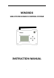
WINDBOX USB JOYSTICK RADIO CONTROL SYSTEM INSTRUCTION MANUAL 1
TABLE OF CONTENTS 1.Introduction ..................................................... 4 2.OverallLayoutofGroundStation .................................. 5 2.1Exterior&Interface ......................................... 5 2.2BasicOperation ............................................. 6 2.3InsertNewJoystick .......................................... 7 2.4ThrottleAlarm .............................................. 8 2.5DefaultsettingofJoystickX52orX52pro ....................
4.9Output16ChannelsofPWMSignalswithUsingTwoReceivers21 4.10FailSafeSetting ........................................... 22 4.11ButtonMonitor ........................................... 23 4.12ButtonMapping .......................................... 24 4.13CancelButtonMapping ................................... 27 4.14ShortcutSettingforUnlockingActionofmulti-rotorcraft .... 28 4.15SetSix-segmentSwitchofAPM/PIXFlyController .......... 30 4.
1. Introduction ThankyouforpurchasingaWINDBOXseriesdigitalproportionalR/C system.Thissystemisextremelyversatileandmaybeusedbybeginners andprosalike.Inorderforyoutomakethebestuseofyoursystemand toflysafely,pleasereadthismanualcarefully.Duetounforeseen changesinproductionprocedures,theinformationcontainedinthis manualissubjecttochangewithoutnotice.
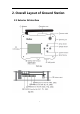
2. Overall Layout of Ground Station 2.
2.2 Basic Operation 1. Screwtheantennaintotheantennainterfacefromthetop,and inserttheUSBflightjoystickintotheUSBinterfaceatthebottomof theequipment,andconnecttheextensioncordfromthepower interfacewiththebatterywhichcanbe2S(8.4V)or3S(12.6V). 2. PressthepowerswitchtoelectrifytheequipmentandtheLCD screenisthereforeturnedon.Atthistime,theequipmentwillstart toworknormally.
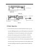
3. Linkthereceivertothecontrolledequipment,andthenthe controlledequipmentcanberemotelycontrolledthroughtheUSB flightjoystick. 2.3 Insert New Joystick WhenthesystemdetectednewUSBjoystick,itwillaskwhetherto activatethenewjoystick.Iftheanswerisyes,thesystemwillclear currentconfigurationandacceptthenewlyinsertedjoystickas primarydevice.
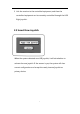
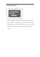
2.4 Throttle Alarm Duringtheinitiationofthesystem,ifthethrottleisnotatthelowest position,thesystemwillalarm,andsuspenduntiltheuseradjustthe throttletothelowestposition.Iftheuserclicked“CloseRF”,theRF systemwillbeshutdowntoprotecttheuserwhenthesystemis initiated.
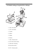
2.5 Default setting of Joystick X52 or X52pro 1. CH6/Twistswitch 2. CH5/Twistswitch 3. Throttle 4. Aileron 5. Rudder 6. Elevator 7. CH8/3Gradesswitch 8. Roll/Pitchmintrimswitch 9. Multi-rotorunlockkey 10. Yawmintrimswitch 11.
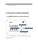
12. Systemmenukey 3. Instruction of Menu Operation 3.1 WINDBOX Buttons for Menu Operation Press“MenuRightButton”toentermainmenuwhenunderthe systemhomescreen.
3.2 System Home Screen A.Atimerisontheleftoftheinformationbar B.InsertedUSBjoystickstatusisinthemiddleoftheinformationbar C.Thebatteryvoltageisontherightoftheinformationbar D.4-channelsdataisinthemiddleofthescreen 3.
Forenteringsub-menu,press“MenuRightButton”whenundermain menu. Sub-menuOperation A.Back:press“MenuLeftButton”toreturntoupperlevelmenu.Press “MenuUp”and“MenuDown”buttonstoselectsub-menu. B.Menuwithoutoptions:press“MenuLeftButton”toreturntoupper levelmenu.Press“MenuRightButton”toentersub-menu. C.Menuwithoptions:press“MenuLeft”and“MenuRight”button tosettheparameters. D.
4. Functions 4.1 Servo Monitor Thisfunctioncanbeusedtomonitorthevaluesofallchannels.Thefirst pageshowsthevaluesofthefirsteightchannels;press“MenuDown Button”tomovetonextpageforthevaluesofothereightchannels. Press“MenuLeftButton”toreturntoupperlevelmenu.
4.2 Trim Setting ●Optionone:selecttargetedchannel ●Optiontwo:thevalueoftrim ●Optionthree:Resettrim.sub-trimisresettotheinitialvalue. 4.3 D/R Setting Thisfunctioncanbeusedtoadjusttheoutputrangeofthechannel. ●Optionone:disableorenableallchannelsdualratefunctions. ●Optiontwo:choosetargetedchannel.
●Optionthree:changetheratevalueofthetargetedchannel.The defaultvalueis100%;adjustablerangefrom50%to150%. 4.4 CH Reverse Setting Thisfunctionreversestheoperationdirectionofthesticks,switches, trimmerlevers,andknobs ● Optionone:choosetargetedchannel ● Optiontwo: "NORM":Normaloperationdirection "Reverse": Operationdirectionisreversed.
4.5 Linear Curve Setting Thisfunctioncanbeusedtoadjustthelinearcurveofspecificchannels. ●Optionone:enableordisablethecurvefunctionsofallchannels ●Optiontwo:choosethetargetedchannel ●Optionthree:selectthepointforformingthecurve(Atotalof5points) ●Optionfour:thevalueofselectedpointinx-coordinate ●Optionfive:thevalueofselectedpointiny-coordinate Therevisedcurvecanbepreviewed. Note: 1.
2.Thex-valueofcurrentpointshouldbelargerthanthex-valueof previouspoint,andsmallerthanthex-valueofnextpoint. 4.
FormixingofacarcontrolleroraUSBsteeringwheel,throttleandbrakepedal shouldbemixedtoamainchannel. 4.7 Receiver Link Procedure Eachtransmitterhasanindividuallyassigned,uniqueIDcode.Inorderto startoperation,thereceivermustbelinkedwiththeIDcodeofthe transmitterwithwhichitisbeingpaired.
2. Open“OutputMode”menu; 3. Option1:select“Built-in2.4G”; 4. Option5:select“12CH-FHSS”; 5. Option6:regeneratetheuniqueIDofcontrollerforavoiding interferencebetweencontrollersinaction; 6. Option2:select“MatchCodeOn”; 7. Turnonthereceiver ; 8. Indicatorlightofthereceiverquicklyflashedfor10timesandturned off. 9. Option2:select“ModeCodeOff”’ 10. Re-electrifythereceiver.
2.PPMmode:theSBUSportofthereceiveroutput theNo.1PPM channel,andCH12portoutputtheNo.2PPMchannel.EachPPM channelcontainseightsignalchannels. ●Howtoswitchthemodeofreceiver: 1.
4.9 Output 16 Channels of PWM Signals with Using Two Receivers ●Areceiveronlyhas12ports.Forenablingoutput16channelsofPWM signals,musttousetworeceivers.The1-12portsofthefirstreceiver canbeoutputCH1-CH12PWMsignalsf;the1-8portsofthesecond receivercanbeoutputCH1-CH8PWMsignals.the9-12portsofthe secondreceivercanbeoutputCH9-CH16PWMsignals. ●Themethodtoset9-12portsofthereceiveroutputCH9-CH16 PWM signalsisasfollows: 1.
2. Judgethecurrentmodeofthereceiver.Iftheindicatorlightslowly flashesforthreetimesafterelectrified,itmeansthereceiveris workinginPWMmode;Iftheindicatorlightslowlyflashesforfour timesafterelectrified,itmeansthereceiverisworkinginPPMmode. 16channelsareonlyavailableinPWMmode. 3. Re-electrifythereceiver,quicklypress“Reset”buttonforfourtimes whentheindicatinglightisflashing.
2. Option1:Select“Build-in2.4G”; 3. Electrifythereceiver,andtheindicatorlightwillbeonconstantly; 4. Keepallchannelsofthejoystickatthepositionatwhichyouwantto initiatefailsafeprotection; 5. Option3:select“FailsafeON”,thentheindicatorlightofthereceiver willbeturnedoff,thenwaitfor2or3seconds; 6. Option3:select“FailsafeOFF”,thentheindicatorlightofthe receiverwillbeturnedonandbesolid,indicatingthatthesettingis successful.
4.12 Button Mapping WINDBOXcanmapanybuttonofthejoysticktoaspecificaction.For instance,a3-segmentswitch,shortcutforunlockmulti-rotorscraft, trimbutton,andsoon.
z Low:Setchannelasathree-stageswitchandsetittoLow z Three-stageSwitch:Setchannelasathree-stageswitch,switchthethreestage byorder. z Two-stageSwitch:Setchannelasatwo-stageswitch,switchthetwostageby order. z Thechannelvalue+:Pressthebutton,thechannelvalueisincreased. z Thechannelvalue-:Pressthebutton,thechannelvalueisdecreased. z Trim+:Pressthebutton,theTrimvalueisincreased.
Note: Ifthechannelwasalreadymappedtojoysticklinearaxis,it’sa musttocancelmappingfirst,otherwise,therewillbeconflict.Theway ofcancelingmappingisreferredtothechapter“CancelMappingto Joysticklinearaxis”. Example1:IfwewanttomapthebuttonofSaitekX52ProJoysticktothe 3-segmentswitchofCH8, 1. Open“ButtonMonitor”menu,pressthefirstbutton,thenwewill observebuttonnumber30flashonthescreen; 2.
Example2:thewaytomapthePOVhatbuttonofthejoysticktothe menubuttonoftheWINDBOXisasfollows(basedonSaitekX52) 1. Firstlyopen“ButtonMonitor”,findthenumberofthePoVhat; 2. Presstheup,down,leftandrightbuttonofPoVhatofthejoystick, thennumber42,43,40and41flashonthescreenrespectively; 3. Returnto“ButtonMapping”menu.Option1SelectbuttonNo.40 . Ignoreoptions2; 4. Select“MenuLeftButton”foroption3.
Forexample:forcancelingthemappingbetweenthebuttonofSaitek X52andCH8, 1. Open“ButtonMapping”menu.Selectbutton30foroption1,and CH8foroption2; 2. Select“Close”foroption3; 3. Refertostep1,settheactionofButton28and29as“Close”; 4. ThenthemappingbetweenbuttonsandCH8iscanceled.Formapping thischanneltojoysticklinearaxisagain,pleaseoperateaccordingto chapter“JoystickLinearaxisMappingSetting”. 4.
●Option2:setholdtimeofunlockingaction. Thewaytorecordspecificunlockingaction: 1.Selectoption1andthenpressrightbuttontorecordtheunlocking action; 2.Keepthejoystickatunlockingpositionspecifiedbyflycontroller,and keepsuchposition; 3.Selectoption1andthenpresspressleftbuttontostoprecording. Note:Pleasekeeptheunlockingpositionuntiltheendofthe recording. Thewaytosetunlockingbuttonshortcut: 1.
bettertoselectabuttonwithcoverasshortcut,forexample,thefire buttonofX52. 4.15 Set Six-segment Switch of APM/PIX Fly Controller ForsixsegmentswitchofAPM/PIX4flycontroller,thesixsegmentcan bemappedtosixbuttons,thustoswitchatanytime.Thismenucanbe usedtorevisethevalueofaspecificgear. ●Option1:1st-6st gear,pressLeftandRightbuttontoselect. ●Option2:ValueofAPMgear.PressLeftandRightbuttontoselect.
4.Select“APM1”foroption3; 5.Refertoabovestepstosetotherfivesegmentsoftheswitch. 4.16 Mapping Linear axis of the Joystick to the Channel WINDBOXcanmapalllinearaxisofthejoysticktospecificchannel. ●Option1:joystickdisplaymenu.Clickittoentersub-menutoviewthe axisnamesofthejoystick; ●Option2:selectthenameoftargetedaxisoftheUSBjoystick; ●Option3:selectthechannelnumbertobemappedtothetargeted axis.
Forexample:formappingtheleftandrightdirectionaxisofjoystick tochannel1, 1.Clickoption1toenterjoystickdisplaysub-menu.Pullthejoystick leftwardsandrightwards,thenwecanfindtheindicatingrodforRX axisisalsomovingleftwardandrightwards.Thenthenameoftheaxis ofthejoystickisRX. 2. Select“RX”foroption2; 3. Select“CH1”foroption3; 4. ThentheRXaxisofthejoystickissuccessfullymappedtoCH1. 4.
4.18 Trainer Setting TheTrainerfunctionmakesitpossiblefortheinstructortochoosewhich channelsaretobeusedforinstruction,makingitpossibletomatchthe trainingabilitytothestudent'sskilllevel.Twotransmitters(eg:another WINDBOX,orFutab,JR,Frysky,WFLYtransmitters)mustbeconnected byanoptionaltrainercord,andtheinstructor'stransmittershouldbe programmedfortraineroperation,asdescribedbelow.
●Option4:selectthedatasource:Joystick,PPMIN. Forexample,forusingaWINDBOXasTrainer,thesettingisasfollowing: 1.Settheoutputoftrainee’sremotecontrollertoPPMsignal,then usetrainercabletoconnecttrainee’s Transmitter withthe WINDBOX; 2.Select“ON”foroption1; 3.Select“PPMIN”foroption4; 4.TurnonTrainerfunction,shakethejoystickofthetrainee.Inthe channeldisplaymenu,youcantracetheactionofthetrainee.
Forexample,ifWINDBOXtobesetastraineecontroller,thetraining functionshouldbedisabled.Whiletheoutputmodeshouldbe changedtoPPMsignaloutput. 1. In“TrainerSetting”menu,select“OFF”foroption1; 2. Open“OutputMode”menu; Setthevalueofoption1from“Built-in2.4G”to“futabaPPM”, thenconnectWINDBOXwithcoachTransmitterviatrainercable. 4.
Settingwithusing2.4GreceiverForward: 1. Set2.4GreceivertoPPMoutputmode(pleaseoperateaccording tochapter“4.8SwitchbetweenPPMandPWMModeofthe Receiver”); 2. ConnecttheSBUSportofthereceiverwiththePPMinputport1of the433Mrangeextender; 3. ConnecttheCH12portofthereceiverwiththePPMinputport2 ofthe433Mrangeextender(iftherangeextenderonlyhaveone PPMinputport,thenskipthisstep); 4. In“OutputMode”ofWINDBOX,select“Built-in2.4G”.
Thesignalwireinthemiddleoftheaudioplugofthesimulatorcable <—>PPMpinofthePPMconnectorofWINDBOX Thegroundingwireattheedgeoftheaudioplugofthesimulator cable <—>GNDpinofthePPMconnectorofWINDBOX 4.21 Low Battery Alarm Setting z Option1:selectalarmvoltage.Ifthevoltageislowerthanthis value,thebuzzerwillalarm.If2Slithiumbatteryisused,pleaseset thisvalueto7v.If3Slithiumbatteryisused,pleasesetthevalue to10.
4.22 Configuration Setting WINDBOXcansavefiveconfigurationformodelaircraftatmost. z Option1:toswitchtheconfigurations.(ifapplythenew configuration,pleasesavetheconfiguration,repoweronthe windbox) z Option2:savecurrentconfiguration. z Option3:resetcurrentconfiguration,alltheconfigurationswillbe cleared.Insertedjoystickwillberegardedasnewdevice. z Option4:displaythesystemversion.
thereisa“beep”tonewhenthethrottleisatthelowestposition,that meansthesystemsavedtherevisedconfigurationautomatically. 4.23 Throttle Setting WhentheThrottleOfffunctionisenabled,thethrottleoutputwill alwaysatthelowest,nomatterwhat’sthepositionofthethrottleaxis ofthejoystick.Thisfunctioncouldprotectuserswhenusinga gasoline-poweredengine.Youcanalsomapabuttontoenableor disablethisfunction.
5.
42