
Winch servo


IRSA Supported 65 Class Rules August 2018 16
PART 3 – APPENDICES
Certification control shall be carried out in accordance with the current ERS
except where varied in Part 3.
Section H – Measurement
H.1 MEASUREMENT
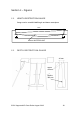
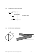
(a) The sail shall be placed over the measurement grid with the
clew point on a grid line and with the head point and tack
point on a line perpendicular to the grid lines. See figures J.6
and J.7.
(b) If the tack point falls above the grid line on which the clew
point is placed, the sail shall be moved vertically until the tack
point is on a grid line. See Figure J.6 and J.7.
(c) The upper limit of area A1 shall be marked at the luff and leech
where they pass over the grid line. See Figure J.6.
(d) Cross widths, c
0
to c
n
, shall be measured from the leech to the
luff at and along all the horizontal grid lines which the sail cuts.
See Figure J.6 and J.7.
(e) Heights, h
0
to h
n
, shall be measured from the grid line to the
foot at and along all the vertical grid lines which the sail cuts.
See Figure J.6 and J.7.
(f) Hollows in the sail edges shall be bridged by a straight line and
cross widths and heights shall be taken to the bridging line. See
Figure J.6.
(g) Linear measurements shall be taken in millimetres and rounded
up to the nearest whole number before being recorded on the
certification control forms and/or certificate, used in
subsequent calculations or compared with a limiting value.
(h) Maximum and minimum values of limitations in the class rules
or certificate shall be taken as absolute limiting values.
H.2 CALCULATION
(a) The major area, A1, is calculated as:
A1 = 50 (c
0
+ c
n
) + 100 (c
1
+ c
2
+ . . . c
n-1
)
(b) The head area, A2, is found from c
n
, c
n-1
and E using a
calculation contained in the measurement form where E is the
height of the sail above the uppermost grid line.
(c) The area below the luff perpendicular, A3, is calculated as:
A3 = 20 (h
0
+ h
n
) + 40 (h
1
+ h
2
+ . . . )
(d) The sum of the areas, As, is calculated as:
As = A1 + A2 + A3