Long Range Wireless OSD 5.
User's Guide Catalogue Product Instruction……………………………………………………………………………3 Features…………………………………………………………………………………………3 Specifications………………………………………………………………………………….4 Channel Frequency……………………………………………………………………………5 Schematic Diagram……………………………………………………………………………5 Interface…………………………………………………………………………………………6 Button Function………………………………………………………………..............………6 OLED Display interface……………………………………………………………………….7 OSD Screen Display interface……………………………………………………………….
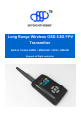
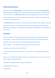
Product Instruction Welcome to enjoy the Skysighthobby 5.8GHz Video Transmitter with OSD. Skyshighthobby products have forged a reputation for quality and reliability and are tested and developed by FPV pilots for FPV pilots. The SKY-S60 transmitter packs a whopping 600mw of ultra clean 5.8GHz power! It can transmit a full range of 32 channels and comes with a clean pre-wired harness; it’s perfect for any long range aircraft.
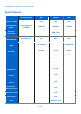
● Suitable for airplanes, cars, and boats Specifications Test conditions Supply voltage Transmission power @T=25degrees 5705MHz Min Typical Max 6.5V 12V 28V 400mW 600mW 750mW Antenna connector Current consumption SMA Jack @voltage12V NA 0.4A 0.6A Temperature range -10 degrees Voltage accuracy ±0.05V ±0.1V ±0.5V Video Bandwidth 5MHz 6MHz 6MHz 80 degrees Impedance 75Ω/1Vp-p Subcarrier 6.5MHz Audio Impedance 4.
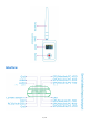
Channel frequency table (32CH): (Unit of frequency: MHz) A B C D 1 5705 5733 5865 5740 2 5685 5752 5845 5760 3 5665 5771 5825 5780 4 5645 5790 5805 5800 5 5885 5809 5785 5820 6 5905 5828 5765 5840 7 5925 5847 5745 5860 8 5945 5866 5725 5880 Schematic diagram: 5 / 14
Interface: 6 / 14
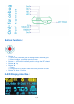
Button function: Button ◀: 1. OLED main interface push to change the RF channel group 2. Menu interface , push back previous menu Button ▶:OLED main interface push to change the RF channel Button ▲:Up Button ▼: 1. Down 2.
Note :The RF power information on OLED display is PA chip detector power , not is actual RF output power OSD Screen display interface: OSD panel 1: OSD panel 2: 8 / 14
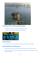
Frequency and channel groups setting: At OLED main interface press button◀ change channel groups At OLED main interface press button▶ change RF channel Home Setting: At OLED main interface long press button ▼ about 3 seconds setting the HOME Switch OSD panel with remote: Switching OSD panel need to connect PPM output signal with remote control receivers Connect to PPM remote control receiver channel and GND wire in the figure below (Switch OSD display mode) 9 / 14
Using the remote control 3-band switch or joysticks can toggle the OSD panel interface PPM<1.2ms is OSD off PPM>1.8ms is OSD panel 2 other PPM>1.3ms and PPM<1.
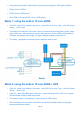
Mode 3: MAVLINK serial data This mode only for MAVLINK protocol's flight controller, ex.
Set the serial interface baud rate GPS Band rate Setting Click OK,select GPS Band rate in the menu , select the baud-rate for GPS in list , typical GPS baud rate is 4800 or 9600 and 19200 Mavlink Band rate Setting Click OK,select Mavlink Band rate in the menu, select the baud-rate for flight controller's Mavlink protocol in list , typical Mavlink protocol baud rate is 57600 PC Bandrate Setting Click OK, select PC Bandrate in the menu , select the baudrate for PC debug in list , typica
IMU Calibrate When use built-in 10-axis AHRS IMU, you need to do built-in IMU calibrate for the first time use or after restoring the factory settings and the flight place is changed Select IMU Calibrate in menu and press OK , follow to the tips on OLED display, press any buttons start calibration of accelerometer and gyroscope after 10 seconds , please hold in a quiescent state , after accelerometer and gyro calibration is completed, OLED screen will prompt calibration of data , after 5 seconds wil
Calibrate will be finish in about 30 seconds Reset Default Setting Choose Reset Default in the menu and press the OK key, it will restore the factory settings After restoring factory settings, depending on the connection mode, please configure the serial data type and baud rate once again , do IMU self test and IMU calibrate if using the built-in AHRS modules View AHRS Data Menu select View AHRS data and confirm , the IMU self test and calibrate values will be display in OLED panel OSD ON/OFF