
User Manual
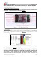

1.3.1 Connection to the Auxiliary Voltage Detection Cable:
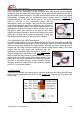
This port has two modes. When the video voltage mode, with the supplied Y cable shown
in Figure 1.12, the A/V link battery is connected to the female JST connector, the A/V
transmitter/ camera is powered up from the male JST connector, for example. And the 2-
pin connector with black and red twisted wire are
connected to the voltage auxiliary port on the
OSD main board.The A/V link battery pack
voltage is detected through this port. When this
port is configured as Receiver Signal Strength
Indication(RSSI) mode, the receiver RSSI output
is connected to this port to feedback the real-time
signal strength of the RC RF link. Please note
that the red pin is the positive voltage, and the
black pin is the ground.
1.3.2 Connection to the Auxiliary Serial Module:
This port is reserved for future development for receiving in-flight instructions from the
ground station via radio modem. The blue/ red/ black pins connect to the data TX/ +5V/
ground of the radio modem module respectively.
1.3.4 Connection to the RC Receiver:
The two PPM auxiliary ports are reserved for future development for receiving in-flight
settings from the RC receiver spare channels via RC link. The orange/ brown pins connect
to the PPM signal out/ ground of the RC receiver channel. The red pin also can be
connected to the 5V supply pin of the RC receiver when it is needed to be powered up by
the OSD main board.
1.3.5 Connection to the Co-pilot Module:
This port is reserved for future development for connection to the Co-Pilot module to
achieve the autonomous flying.
1.4 Other Interfacings:
1.4.1 Status LED:
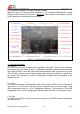
There is a red LED on the up-right of the OSD main board. After a successful power up of
the OSD main board, the LED will be indicating a slow flashing to indicate the normal
operation of the Apache OSD system. When downloading the firmware to the main board
via USB data module, this LED should fast blinking which indicating the firmware fresh on-
going.
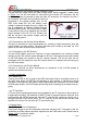
1.4.2 TF Card Slot:
A TF card (to be supplied separately) can be installed to the TF card slot for the purpose of
in-flight data recording. The maximum of 8GB TF card is supported and the card has to be
pre-formatted with FAT32 before use. Slot the TF card with the contact pins facing up, or
facing the printed circuit board (PCB). The TF card will not be well sit into the slot if the
direction is in-correct. Do not force the TF card into the slot.
1.5 Special Note:
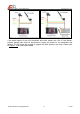
1.5.1 OSD and A/V Link Connection:
If the power supply of your A/V transmitter and video camera are 5V. The power of the A/V
transmitter and video camera could be supplied from the OSD main board. Please refer to
Figure 1.13 for connection details.
AEO TECHNOLOGY www.aeorc.cn
Entire Contents © Copyright 2010 8 V1.03