
User Manual
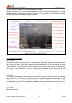

camera and/ or A/V transmitter when necessary. Please do not connect this pin to the A/V
link VCC if it is a 12V system. The black is the common ground of the A/V link. It is
suggested to place a ferrite coil near the connector to filter the noise to prevent OSD
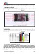
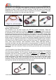
image distortion. This 4-pin connector cable is supplied as per shown in Figure 1.3. Please
note that the ground/ black is on the most right of this port.
1.2.2 Connection to the GPS
Module/ USB Data Module:
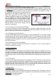
This connector is for the GPS module and USB data module connection. These two
modules are supplied in this kit as shown in Figure 1.4 and Figure 1.5, and they must not
be connected to the OSD main board simultaneously. When GPS module is connected,
the black/ red/ blue pins connect to the ground/ +3.3V/ data TX of the GPS module, which
are the black/ red/ blue wire of the GPS module receptively. The forth pin marked with
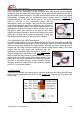
white is not connected at this time. The GPS module must be placed on the plane with the
sticker facing up towards the sky without any blocking (especially blocked by conductive
material, such as metal and carbon-fiber) to maximise the GPS satellite signal reception.
And make sure the GPS module is kept away from the power/ RF components such as
motor, motor speed controller, radio transmitter/ receiver. When USB data module is
connected, the black/ red/ white pins connect to the ground/ data TX/ data RX of the USB
data module, which are the black/ red/ blue wires of the USB data module. The second pin
marked with red is not connected. Please note that the ground/ black pin is on the most left
of this port.
1.2.3 Connection to the Infrared Sensor Module:
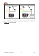
This connector connects the infrared (IR) receiver module for the reception of the IR signal
from the remote controller. The IR receiver module shown in the Figure 1.6 must be
connected, and the IR remote controller shown in Figure 1.7 must be pointed to the IR
receiver module reception window in hemispherical shape when performing the OSD
system configuration. The black/ red/ blue pins connect to the ground/ +3.3V/ data output
of the IR receiver module, which are the black/ red/ blue wire of the IR receiver module
receptively. Please note that the ground/ black pin is on the most left of this port, and the
most right pin marked with white should not be connected.
AEO TECHNOLOGY www.aeorc.cn
Entire Contents © Copyright 2010 6 V1.03