
User Manual

AEO Apache OSD Pre-Release Evaluation Version Manual
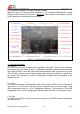
1, Hardware Connections
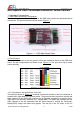
1.1 Main Board Interfacing Configuration:
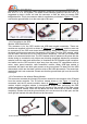
There are two groups of the connections for the OSD main board to be interfaced with its
accessories. The port functions are shown as per Figure 1.1:
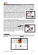
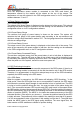
1.2 Port Group A:
There are 8 connectors in the port group A, which are located on the left of the OSD main
board. The pin configurations are shown as per Figure 1.2. The ports from top to button
are as following:
1.2.1 Connection to the Audio/Video (A/V) Link:
The white pin shown in Figure 1.2 connects to the audio channel of the A/V transmitter to
transmit the in flight data to the ground station. The ground receiver could then connect the
audio channel to the USB Audio Interface (to be supplied separately) to monitor the in-
flight data in the windows software (e.g., Google Map). The yellow pin parallels with the
video channel of the A/V transmitter and the video camera to overlay the On-Screen-
Display(OSD) image with letters and graphs. The red pin is the 5V output to the 5V
AEO TECHNOLOGY www.aeorc.cn
Entire Contents © Copyright 2010 5 V1.03