
User Manual
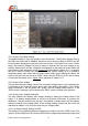

3.1.3 Home Distance Mode Setting
The home distance mode can be set between “Line of Sight” distance mode and “Ground”
distance mode. If “Line of Sight” distance mode is chosen, the true distance between
home and the plane will be displayed with consideration of ground distance and altitude. It
will not take account of the altitude into calculation, but measure the ground distance only
if the “Ground” distance mode is selected. It is not recommended to choose the “Ground”
distance mode if no RSSI system is applied. In some circumstances, especially the plane
is flying too high, although the plane looks not “out of range” from the reading of the
ground distance. But it may have risk of losing control for the RC link, as the displayed
distance might be far less than the true distance.
3.2 Power Battery Settings
There are two sub-menus for the power battery settings. You may use the right arrow
button or enter button to enter the selected sub menu.
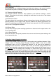
3.2.1 Power Battery Fuel Gauge Setting
There are two item in this sub-menu. The maximum voltage is setting the upper voltage for
the fully charged power battery pack. The minimum voltage is setting the lower voltage for
the fully drained power battery pack. You may press the exit or back button on the remote
controller to quit this sub-menu. The power battery fuel gauge described in section 2.2.2 is
calculated according to this two settings. If the measured voltage of power battery pack is
equal to the set maximum voltage, the fuel gauge will display full bar. If the power battery
voltage drops and the minimum voltage is reached, the fuel gauge display will be flashing,
which warns the pilot the power battery is fully drained, and must land the plane
immediately.
3.2.2 Power Battery Sensor Calibration
You may calibrate the displayed power battery voltage and current by setting offsets in this
sub-menu. There are two options inside, the voltage offset and current offset. It is strongly
recommended to connect an accurate multi-meter to perform this calibration. Connect the
power battery into system, and parallel a voltage meter with the power battery, adjust the
setting of the voltage offset, let the voltage reading at the lower left screen to be the same
as your voltage meter. Similarly, connect the power battery into system, and series a
current meter into the power supply loop, adjust the setting of the current offset, let the
current reading at the lower left screen to be the same as your current meter. Press the
exit or back button on the remote controller to quit this sub-menu.
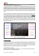
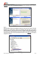
3.3 Auxiliary Voltage Port Settings
There are five settings in the auxiliary voltage port sub-menu to adjust the function of the
physical auxiliary voltage detection port on the OSD main board as per described in
chapter 1.3.1. This sub-menu is shown as per Figure 3.2.
AEO TECHNOLOGY www.aeorc.cn
Entire Contents © Copyright 2010 16 V1.03