
User Manual

2.1.4 Temperature
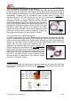
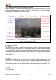
Once the temperature sensor module is connected to the OSD main board, the
temperature sensed by the module will be shown on the top of the screen. The
temperature unit can be selected in the OSD configuration menu or via PC configuration
software between °C and °F.
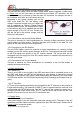
2.2 Power Battery Information
2.2.1 Power Battery Voltage
The voltage of the power battery is displayed on the bottom-left of the screen. This value is
sensed by the power module in real-time. And the reading can be calibrated in the OSD
configuration menu or via PC configuration software.
2.2.2 Power Battery Gauge
The real-time fuel gauge of power battery is shown on the screen. The system will
calculate the fuel gauge of the power battery pack according to the set maximum and
minimum voltage range described in section 3.2.1. The fuel gauge has an liner relationship
with the set voltage range.
2.2.3 Power Battery Current
The output current of the power battery is displayed on the bottom-left of the screen. This
value is also sensed by the power module in real-time. And the reading can be calibrated
in the OSD configuration menu or via PC configuration software.
2.2.4 Power Battery Consumed Energy
The real-time consumed energy from the power battery in unit of mA-Hour is displayed in
this area as well. The pilot will have an idea of how much energy left in the battery pack
by calculating the battery full capacity minus this value. This reading will be accumulated
since the power on of the system, and will be reset once power off.
2.3 GPS Positioning Information
The GPS module is one of the most essential component of the OSD system. If there is no
associated sensing module is connected, all the real-time data is rely on the GPS module.
Therefore, it is recommended for the pilot to always keep an eye on the GPS information,
especially the HDOP reading in the GPS status.
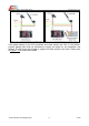
2.3.1 GPS Status
When the system is powered up, the GPS status will indicating “GPS Searching...” in the
initial period. Once the GPS signal from one or more satellite is received, the GPS status
will indicate the received signal strength of each satellite in form of vertical bars. The GPS
is trying to lock the position during this time. You must not take off the plane during this
time. If the connection between GPS module and OSD main board is interrupted before
the GPS position is locked, the screen will show “GPS Fail”. Once the position is locked by
the GPS successfully, the GPS status will indicating the value of the calculated horizontal
dilution of precision (HDOP). The HDOP is the index that measures accuracy of the GPS
horizontal position. If the value is very close to 1, it means the position located by the GPS
is highly accurate. The position will not be reliable if the reading is more than 6 in general.
It is not recommended to take off the plane if this reading is more than 3. The signal bars
beside the HDOP value is the GPS signal quality indication. The more signal bars, the
better number of GPS satellites are utilised for position locking.
AEO TECHNOLOGY www.aeorc.cn
Entire Contents © Copyright 2010 11 V1.03