AEO TECHNOLOGY www.aeorc.cn 1, Hardware Connections! 5 1.1 Main Board Interfacing Configuration:! 5 1.2 Port Group A:! 5 1.2.1 Connection to the Audio/Video (A/V) Link:! 5 1.2.2 Connection to the GPS Module/ USB Data Module:! 6 1.2.3 Connection to the Infrared Sensor Module:! 6 1.2.4 Connection to the Accessory Sensor Module:! 7 1.2.5 Connection to the OSD Power Module:! 7 1.3 Port Group B:! 7 1.3.1 Connection to the Auxiliary Voltage Detection Cable:! 8 1.3.
AEO TECHNOLOGY 2.4.2 Direction Heading! www.aeorc.cn 12 2.4.3 Home Direction! 12 2.4.4 Relative Altitude! 12 2.4.5 Altitude Scale! 12 2.4.6 Climb Rate! 13 2.4.7 Maximum Altitude Reached! 13 2.4.8 Distance to Home! 13 2.4.9 Speed Scale! 13 2.4.10 Speed Reading! 13 2.5 Auxiliary Voltage Detection Information! 13 2.5.1 Auxiliary Voltage Status! 13 2.6 Miscellaneous Function Information! 14 2.6.1 Horizontal Datum! 14 2.6.
AEO TECHNOLOGY www.aeorc.cn 4.2 Before Taking-Off! 19 4.3 After Taking-Off! 19 4.4 After Landed! 19 5, PC Configuration Software! 20 5.1 USB Data Module Driver Installation! 20 5.1.1 Pre-Installation Preparation! 20 5.1.2 Installation Steps! 20 5.2 Hardware Connection! 22 5.3 Software Interface Introduction! 22 5.3.1 COM Port Setting! 22 5.3.2 OSD Main Board Information! 22 5.3.3 OSD In-Flight Interface Screen Monitor! 23 5.4 OSD Main Board Firmware Update! 23 5.
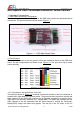
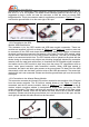
AEO TECHNOLOGY www.aeorc.cn AEO Apache OSD Pre-Release Evaluation Version Manual 1, Hardware Connections 1.1 Main Board Interfacing Configuration: There are two groups of the connections for the OSD main board to be interfaced with its accessories. The port functions are shown as per Figure 1.1: 1.2 Port Group A: There are 8 connectors in the port group A, which are located on the left of the OSD main board. The pin configurations are shown as per Figure 1.2.
AEO TECHNOLOGY www.aeorc.cn camera and/ or A/V transmitter when necessary. Please do not connect this pin to the A/V link VCC if it is a 12V system. The black is the common ground of the A/V link. It is suggested to place a ferrite coil near the connector to filter the noise to prevent OSD image distortion. This 4-pin connector cable is supplied as per shown in Figure 1.3. Please note that the ground/ black is on the most right of this port. 1.2.
AEO TECHNOLOGY www.aeorc.cn 1.2.4 Connection to the Accessory Sensor Module: There are total four connectors can be connected with AEO Apache sensor modules. These four ports are having the same function. Any of them can be connected with any of the AEO Apache sensor modules. The OSD main board will detect the type of the module automatically. Currently, only the temperature sensor module shown in Figure 1.9 is supplied with this kit.
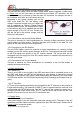
AEO TECHNOLOGY www.aeorc.cn 1.3.1 Connection to the Auxiliary Voltage Detection Cable: This port has two modes. When the video voltage mode, with the supplied Y cable shown in Figure 1.12, the A/V link battery is connected to the female JST connector, the A/V transmitter/ camera is powered up from the male JST connector, for example. And the 2pin connector with black and red twisted wire are connected to the voltage auxiliary port on the OSD main board.
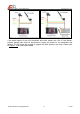
AEO TECHNOLOGY www.aeorc.cn If the power supply of your A/V transmitter and video camera are 12V. A 3-cell lithiumpolymer battery pack must be introduced to supply the power for the transmitter and camera. The 5V power will not able to support the video system in the case. Please refer to Figure 1.14 for connection details. Entire Contents © Copyright 2010 9 V1.
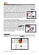
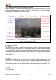
AEO TECHNOLOGY www.aeorc.cn 2, On-Screen-Display In-Flight Interface Screen When the system is connected and powered up. The On-Screen-Display(OSD) in-flight interface screen should be as shown in Figure 2.1. The functions of the display contents will be described in the following of this chapter. 2.1 General Information 2.1.1 Timer The timer can be used for measure the duration of the flight. There are two activation mode of this timer.
AEO TECHNOLOGY www.aeorc.cn 2.1.4 Temperature Once the temperature sensor module is connected to the OSD main board, the temperature sensed by the module will be shown on the top of the screen. The temperature unit can be selected in the OSD configuration menu or via PC configuration software between °C and °F. 2.2 Power Battery Information 2.2.1 Power Battery Voltage The voltage of the power battery is displayed on the bottom-left of the screen. This value is sensed by the power module in real-time.
AEO TECHNOLOGY www.aeorc.cn 2.3.2 Position Coordinate The current coordinate positioned by GPS is shown on the bottom-right corner. The upper value is the , and is on the bottom. You will observe these two values are keep updating during the flight as your plane is keep moving in the air. In case the GPS module connection is broken, the latest position coordinate will be frozen to remind pilot the position that the GPS positioning is lost.
AEO TECHNOLOGY www.aeorc.cn 2.4.6 Climb Rate By calculating the rate of altitude change, the climb rate is shown on the screen. A positive value means the plane is climbing. A negative value means the plane is descending. 2.4.7 Maximum Altitude Reached The maximum altitude reached is keep updated by the maximum reading of relative altitude. This value can be reset by pressing the reset button in red color on the infrared remote controller. 2.4.
AEO TECHNOLOGY www.aeorc.cn 2.6 Miscellaneous Function Information 2.6.1 Horizontal Datum The horizontal datum can be activated and switched off via PC configuration software. It is acted as the horizontal level reference of the viewed picture. 2.6.2 Flight Recorder Status Once a formatted TF card is inserted to the OSD main board, the flight recorder status will be indicating “TF Card Ready” in “landed” mode.
AEO TECHNOLOGY www.aeorc.cn 3, On-Screen-Display Configuration Menu The OSD system must be configured before taking-off the plane. Most of the system configuration setting could be performed in the On-Screen-Display configuration menu via infrared remote controller. Before starting the configuration, please make sure the infrared beam from infrared remote controller is able to reach the hemispherical shaped window on the infrared sensor module.
AEO TECHNOLOGY www.aeorc.cn 3.1.3 Home Distance Mode Setting The home distance mode can be set between “Line of Sight” distance mode and “Ground” distance mode. If “Line of Sight” distance mode is chosen, the true distance between home and the plane will be displayed with consideration of ground distance and altitude. It will not take account of the altitude into calculation, but measure the ground distance only if the “Ground” distance mode is selected.
AEO TECHNOLOGY www.aeorc.cn 3.3.1 Auxiliary Port Mode Setting The default setting of the mode setting is “Not Connected”. The Auxiliary Voltage Port on the OSD main board will be disabled, and there will not be any voltage or RSSI of the RC link information displayed on the lower-left of the screen.
AEO TECHNOLOGY www.aeorc.cn is lowest. You may connect and power up the system, turn off and move alway all RC transmitter from the RC receiver, and set this voltage value according to the real time detected auxiliary voltage. 3.3.5 Full Signal Voltage Setting for RSSI This setting is also only applicable when the auxiliary port mode is set to the “RSSI” mode. This value is set according to the RC receiver RSSI output voltage when transmitter signal level is highest.
AEO TECHNOLOGY www.aeorc.cn 4, General Operation 4.1 Before Powering-Up the System All connection must be made before powering up the system. Ensure the GPS antenna is facing up and not blocked from the sky. Make sure all components are securely fixed in the plane. The GPS must be kept away from all electronic components, especially the electrical speed controller, video transmitter and wireless modem transceiver. 4.
AEO TECHNOLOGY www.aeorc.cn 5, PC Configuration Software 5.1 USB Data Module Driver Installation 5.1.
AEO TECHNOLOGY www.aeorc.cn this device driver has not yet passed Windows XP Logo compatibility as per shown in Figure 5.4. Click on the Continue Anyway to continue. Step 7 -: After the system finishes the installation process, you may open the “System” from the Windows XP™ control panel. Choose the “Hardware” tag, and click on the “Device Manager” (Might be different for other version of windows).
AEO TECHNOLOGY www.aeorc.cn You may also reference the driver installation and un-installation instructions from the Prolific Technology Inc. Website PL2303 User Manual Page. 5.2 Hardware Connection After the driver software is proper installed, and the USB Data Module is plugged into the PC USB port. Then, the serial cable connector from USB Data Module can be connected to the Apache OSD main board.
AEO TECHNOLOGY www.aeorc.cn 5.3.3 OSD In-Flight Interface Screen Monitor The content in the In-Flight Interface Screen Monitor is identical as you will observed in the Video system. It can be used as a reference for OSD main board configuration. 5.3.4 OSD Configuration Option Cards There are two option cards for the PC Configuration Software. Most of the settings are performed in the General Setting Option Card. The Auxiliary Port Option Card is for the Auxiliary Voltage Detection Port specifically. 5.
AEO TECHNOLOGY www.aeorc.cn 5.5 General Setting The settings performed in this section are very similar to the On-Screen-Display Configuration Menu. Some configuration options can be only performed here other than the On-Screen-Display Configuration Menu described in Chapter 3. You may refer to Figure 5.9 for a general description of the General Setting option card. 5.5.1 Power Battery Gauge Settings This setting is the same as the Power Battery Fuel Gauge Setting described in the section 3.2.1. The Max.
AEO TECHNOLOGY www.aeorc.cn 5.5.2 OSD Video Display Settings The OSD information display on the screen can be adjusted by the three setting options here. The horizontal offset, vertical offset and the contrast tuning can be performed as the same as the OSD Video Display Setting described in the section 3.4.2. 5.5.3 In-Flight Interface Options The In-Flight Interface Options is not available in the On-Screen-Display Configuration Menu.
AEO TECHNOLOGY www.aeorc.cn 5.5.4 Timer Trigger Options This option sets the trigger criteria of the timer on the top-left corner of the OSD in the OnScreen-Display In-Flight Interface Screen as described in the section 2.2.1. It can be selected between the “Power-On Start”, which the timer will be started when the OSD is powered up, and the “Take-Off Start”, which the timer will be started when take-off of the plane is detected by the system.
AEO TECHNOLOGY www.aeorc.cn General Setting Option Card. although the options available here are the same as described in the section 3.3, but as compared to the On-Screen-Display Configuration Menu, the settings can be performed in a more convenient manner. The general outlook is shown as per Figure 5.13. 5.6.1 Auxiliary Port Mode Setting This setting acts the same function as Auxiliary Port Mode Setting in the On-ScreenDisplay Configuration Menu described in section 3.3.1.
AEO TECHNOLOGY www.aeorc.cn 5.6.2 Auxiliary Port Voltage Calibration The voltage detected by auxiliary port can be calibrated by drag the slide bar, which is the same as the Auxiliary Port Voltage Calibration in the On-Screen-Display Configuration Menu described in section 3.3.3. This can be performed anytime by observing the measured voltage at the bottom of the Auxiliary Port Option Card. 5.6.3 RSSI Signal Voltage Range Setting The Full and Low Signal Voltage Settings for RSSI reading can be set here.