
User Manual


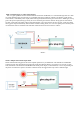
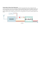
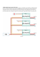


Mode 10: remote control constant cascade working mode
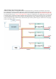
Connection diagram is as the following: before it is powered, short connect all the B and R on all the trigger button, and
all the cables for remote control are connected in parallel, only signal cable and earthed cable are connected with re-
ceiver, driver module group and receiver gets its own battery pack for power supply. When the corresponded channel on
transmitter is pulled to mid gear, all the modules will be on half power output, when it is pulled to up gear, all the mod-
ules will be on full power output, no limitation for 30 seconds’ or 5 minutes’ protection, in this case, user should pay at-
tention to the risk of running down the battery because of long time working, the working mode is similar to mode 5.
Mode10
5) Indicator light
GENERAL USE GLOW PLUG DRIVER gets two indicator lights in total, one is on the button, the other is on PCB, the
display meaning of the two indicator lights is same, the working states are the following:
1, Constant on: full power trigger
2, Flash slowly, on for 0.75 second, off for 0.25 second: stable working mode trigger.
3,Standby, on for 0.2 second, off for 2 seconds, standby mode, means not working under any working modes.
4, Glow plug is short connected, flash two times constantly, stop for 1 second, circulated one after another, it reminds
user to check or change glow plug, and the module doesn’t work anymore.
5, Glow plug is disconnected, flashes three times constantly, stop for 1 second, circulated one after another, it reminds
user to check or change glow plug, and the module doesn’t work anymore.
6, Short press trigger time lag, on for 0.5 second, off for 0.5 second.
7, Long press trigger time lag, on for 1 second, off for 0.5 second.