
User Manual


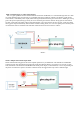
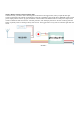


Mode 9: Constant output cascade working mode
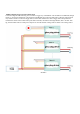
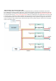
The connection diagram is as the following. Before it is powered, the signal cable B and R on the trigger button of each
module need to be short connected, all the cables for remote control need to be connected in parallel, one control switch
SW needs to be added.
Under this working mode, no limitation for time lag and auto turn off, as soon as SW is turned on, all the drivers will be
on full power output constantly till it comes overheat protection or the battery is run down, this working mode is similar
with mode 4.
Mode 9