
User Manual

11/04/08
4
PD-60357
IR3802AMPbF
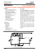
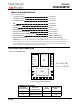
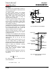
Pin Description
Pins 4, 5 and 15 need to be connected together on system board.
Pin Name Description
1 NC No Connect
2 Fb Inverting input to the error amplifier. This pin is connected directly to the
output of the regulator via resistor divider to set the output voltage and
provide feedback to the error amplifier.
3 Comp Output of error amplifier.
4 AGnd Signal ground for internal reference and control circuitry.
5 AGnd Signal ground for internal reference and control circuitry.
6 SS/SD Soft start / shutdown. This pin provides user programmable soft-start
function. Connect an external capacitor from this pin to signal ground
(AGnd) to set the start up time of the output voltage. The converter can
be shutdown by pulling this pin below 0.3V.
7 OCSet Current limit set point. A resistor from this pin to SW pin will set the
current limit threshold.
8
V
CC
This pin provides biasing voltage for the internal blocks of the IC. It also
powers the low side driver. A minimum of 0.1uF, high frequency
capacitor must be connected from this pin to power ground (PGnd).
9 NC
No Connect
10 PGnd Power Ground. This pin serves as a separated ground for the MOSFET
drivers and should be connected to the system’s power ground plane.
11 SW
Switch node. This pin is connected to the output inductor
12
V
IN
Input voltage connection pin
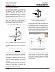
13 HG This pin is connected to the high side Mosfet gate. Connect a small
capacitor from this pin to switch node (SW).
14
V
C
This pin powers the high side driver and must be connected to a voltage
higher than input voltage. A minimum of 0.1uF high frequency capacitor
must be connected from this pin to the power ground (PGnd).
15 AGnd Signal ground for internal reference and control circuitry.