
User Manual

11/04/08
10
PD-60357
IR3802AMPbF
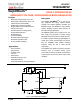
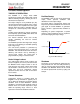
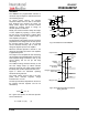
Over-Current Protection
The over-current protection is performed by
sensing current through the R
DS(on)
of the low
side MOSFET. This method enhances the
converter’s efficiency and reduces cost by
eliminating a current sense resistor. As shown in
figure 7, an external resistor (R
SET
) is connected
between OCSet pin and the inductor point which
sets the current limit set point.
The internal current source develops a voltage
across R
SET
. When the low side MOSFET is
turned on, the inductor current flows through the
Q2 and results a voltage which is given by:
Fig. 7: Connection of over current sensing resistor
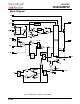
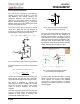
Fig. 8: 3uA current source for discharging
soft-start capacitor during hiccup
An over-current is detected if the OCSet pin goes
below ground. This trips the OCP comparator
and cycles the soft start function in hiccup mode.
The hiccup is performed by charging and
discharging the soft-start capacitor in a certain
slope rate. As shown in figure 8 a 3uA current
source is used to discharge the soft-start
capacitor.
The OCP comparator resets after every soft start
cycle. The converter stays in this mode until the
overload or short circuit is removed. The
converter will automatically recover.
)) --(I(R)R(IV
LDS(on)OCSetOCSetOCSet
2∗−∗=
0)I(R)R(IV
LDS(on)OCSetOCSetOCSet
=∗
−
∗=
)3 --(
R
IR
II
onDS
OCSetOCSet
criticalLSET
)(
)(
∗
==
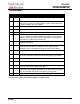
Fig. 9: OCset pin during normal condition
Ch1: Inductor point, Ch3:OCSet
The value of R
SET
should be checked in an actual
circuit to ensure that the over-current protection
circuit activates as expected. The IR3802A
current limit is designed primarily as disaster
preventing, and doesn't operate as a precision
current regulator.
The critical inductor current can be calculated by
setting:
I
OCSet
*R
OCSet
Blanking time
Deadtime
Clamp voltage
The OCP circuit starts sampling current when the
low gate drive is about 3V. The OCSet pin is
internally clamped about 1.5V during on time of
high side gate to prevent false trigging, figure 9
shows the OCSet pin during one switching cycle.
As shown, there is about 150ns delay to mask
the dead time. Since this node contains switching
noises, this delay also functions as a filter.