
User Manual

AEO TECHNOLOGY www.AEOrc.com
Entire Contents © Copyright 2011
1
AEO G-OSD User Instruction Manual
Product Introduction:
Welcome to use AEO GPS-OSD,which is specially designed for micro electric-powered plane with
following features:
● GPS coordinate display, time display, airspeed display
● voltmeter and stopwatch
● RSSI receiver signal strength detection
● Programming the display content
● Support NTSC and PAL TV signal
● Support anti-glare shade control signal
● Support manual calibration
1. Hardware Specification:
Weight: main board 4.6g GPS module 22g
Size: main board 34mm*20mm*4mm GPS Module 35mm*35mm*5mm
Working Voltage:G-OSD 7.4V-12V GPS Module 5V
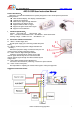
2. Connection & Button Introduction:
2.1 BATT1—Power Supply Port:
G-OSD power supply port, commonly parallel with power
battery.
2.2 BATT2—Auxiliary Equipment Voltage Detection Port
(Auxiliary):
Detect the equipment voltage connected to this port, and
used to measure auxiliary equipment voltage.
2.3 RSSI—Receiver Signal Strength Detection
Detect the signal strength pin voltage value on RC
receiver signal decode chip, the user can know the RC
receiver wireless signal strength from RC transmitter by this
voltage value.
2.4 GPS—Global Position System Module Port
Connect the GPS module for positioning, measure the speed and time.
2.5 Video—Video Overlay Port:
Be responsible for outputting the overlaid video signal to video port equipment.
Suggested Connection Picture: