
User Manual

Mixer Editor
This menu lets you adjust where and how much signal the motors gets from the sticks and sensors.
This enables you to make any configuration possible, with up to 8 motors or servos.
To change between the output channels 1-8, press CHANGE when the upper right number is
highlighted.
• Throttle – Amount of throttle command. Usually 100% if the output channel is connected to
an ESC.
• Aileron – Amount of aileron/roll command. Use positive value for motors on the right side of
the roll axis, and negative for the left side of the roll axis. The value is given by the motor's
distance from the roll axis. More is further away.
• Elevator – Amount of elevator/pitch command. Use positive value for motors on the front
side of the pitch axis, and negative for the back side of the pitch axis. The value is given by
the motor's distance from the pitch axis. More is further away.
• Rudder – Amount of rudder/yaw command. Usually 100%. Use a positive value for a CW
spinning propeller, and negative for a CCW spinning propeller. This is a very important
setting for reversing the servo direction on tricopters. If your tricopter starts to pirouette on
take off, select the channel that the servo is connected to (usually output 4 or 7) and change
the Rudder value from +100 to -100.
• Offset – Applies a constant offset to the channel. Keep this zero when it is an ESC channel,
and around 50% when connected to a servo. Fine tune servo position by adjusting this value.
• Type – Set it to the type (servo or ESC) connected to the channel.
o For ESC: Output PWM rate is always high. Normally outputs zero when disarmed or
throttle is at idle. Applies the "Minimum Throttle" value from the "Misc. Settings 1"
sub-menu when armed and throttle is above zero or when Spin on Arm is “Yes”.
o For Servo: Output PWM rate can be high or low. Outputs the offset value when
disarmed.
• Rate – High rate (400Hz) for ESC or digital servos, or low rate (50Hz) for analogue servos.
• See Appendix F for more information.
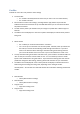
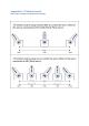
Show Motor Layout
Displays a graphical representation of the motors and servos
• Can be used to check the Motor direction and which outputs to connect the ESCs and Servos
to. Note that this does not set the motor direction. That is set by the wires connected
between your motor and ESC. If you need to reverse your motor, reverse two of the three
motor wires.
• Enables you to see which Motor Layout you have selected and any changes you make in the
Mixer Editor.