
User Manual

This document was written by Chris Hansen.
For more information, or to purchase the products shown here, please visit our web site:
www.hansenhobbies.com
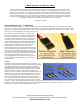
Resistance and Voltage Drop
Since I get so many questions/comments on
wiring for high demand applications like high-
draw systems, high torque digital servos, long
servo leads, and quality of contacts, I though I
would write a section that talks about power
considerations in these situations.
Resistance in the System:
In order to keep your servos and electronics
working at their best, you need to keep the
resistance down in your connections. This
means using suitably sized wire, making runs as
short as possible, and reducing the number of
connections.
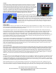
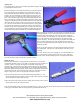
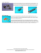
I was curious about the contact resistance for the gold connectors we sell, but manufacturers
don’t often supply these numbers (usually only a current rating). I set to work on an experiment
to measure it: I figured in order to detect it accurately I would need to measure a bunch of
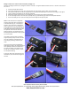
them together, so I made up a 100 contact connector using a bunch of 1x10 housings with the
back eighth of an inch cut off to expose the rear of the terminals. One side was filled with male
and the other with female terminals then I soldered the rear wings of every other terminal
together and added banana plugs on the first and last terminal. This gave me 100 male to female
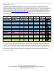
contacts in series, a good sample set. I connected the chain to a precise power supply and
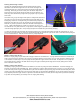
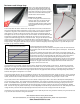
measure voltage drop across the chain for various currents up to 5A and then I graphed Current vs Voltage (divided by 100 to get the voltage
drop per contact). The graph is shown below and you can use it to find the voltage drop across a single contact. If you take the slope of the
I/V graph, you get resistance: 5.625mΩ
A few things should be noted about this study:
1) We’re assuming that most of the resistance in the system is from the contacts and that
the resistance within the metal itself and the solder joints is relatively low. This seems like
a safe bet.
2) The contact resistance may change after a given number of cycles (plug & unplug). My
guess here is that it might go down a tiny bit after a few cycles rubs away any oxidation and
surface debris, stay flat for, who knows, 100 cycles, then start to go up as the contact is
cycled so much that it loses it’s springiness and the gold coating starts to rub off.
3) This study shows the resistance between a male and female crimp pin, but the resistance
between a female connector pin and the solid square header pin found in your receiver may
be different. My guess is that the latter is slightly lower because the flat sides of the
square pin offers more surface area.
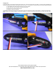
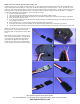
Let’s apply this data to an example. Suppose we have a battery, plugged into a switch plugged, into the receiver. We also have a high-torque
digital servo in our wing with a 12” lead that’s connected to the receiver via two 24” servo extensions. Every time there’s a connection in this
system, there are two contacts, and current has to flow through both of them to get back to its source. In this setup we have 6 connectors for
a total of 12 contacts. If the servo were to surge 3 amps we can see in the graph above that each contact in the loop will drop about 0.017V,
and all of them together will drop 0.017 x 12 = 0.204V.
Let’s further suppose that all of the wire is 24AWG wire and there is 20” on the battery/switch side, and 60” for the servo. Again, current has
to flow through the positive wire and back through the negative wire, so we really have 160” of wire. 24AWG wire has 25.7Ω of resistance per
1,000ft, so there is about 0.343Ω of resistance in our system. Given a 3A draw, we would see a voltage drop of 3 x 0.343 = 1.03V.
As you can see, when our servo demanded 3A of current it also saw a voltage drop of 1.234V. This is about a 18-25% power loss depending on
your receiver battery voltage. If we redid the math with 22AWG wire, and a custom 43” extension for the servo, that voltage drop becomes
0.740V. Use 20AWG and the drop is 0.515V. As a final trial, let’s scratch the whole extension idea and instead just open up our servo and
solder in a new 20AWG 55” lead. We’ll also toss the switch and just plug our battery straight into the receiver using doubled up 6” 20AWG
leads. The same 3A surge only causes a 0.344V drop. In this example keep in mind that we only considered one servo. When multiple servos are
running the battery connection becomes especially important because all of the current is being sourced from that one point.
The idea here is not to tell you exactly how to wire your plane, but to make the point that wiring can make a difference, and give some basic info
so you can make smart decisions on wiring and connections.
.1" Male/Female Contact Voltage Drop
0V
0.01V
0.02V
0.03V
1A 2A 3A 4A 5A