HL200 ML-134311 Page 1 - English Page 33 - French Page 67 - German INSTALLATION AND OPERATION MANUAL MANUEL D’INSTALLATION ET D’UTILISATION INSTALLATIONS UND BEDIENUNGSANLEITUNG F-34941 (Oct 2005)
English / Contents Section Page Safety Information 1.0 4 Safety Guidelines 1.1 4 Warning Symbols 1.2 4 Liability 1.3 5 Foreword 2.0 5 General Information 3.0 5 Caring for our Environment 4.0 5 Packing Material 4.1 5 Disposal of your old appliance 4.2 5 Safety Instructions 5.0 5 Dust Hazard 5.1 6 Never 5.2 6 Always 5.3 6 Attachment Safety Instructions 5.4 7 Using the Mixer 6.0 7 Operating for the First Time 6.1 7 Mixer Component Identification Fig.
Using the Attachment Facility 6.13.1 22 Splash Cover 6.13.2 22 Bowl Scraper Attachment 6.13.3 22 Cleaning 6.14 22 Cleaning after Use 6.14.1 22 Installation and commissioning 6.15 23 Overall Dimensions Fig. 15 23 Technical Information Table 1 24 Unpacking and Handling 6.16 24 Location 6.17 25 Electrical Installation 6.18 25 Operator Training 6.19 26 Mixer Maintenance 7.0 26 Lubrication 7.1 26 Slideways 7.1.1 26 Planetary Seal 7.1.2 27 Bowl Locking Mechanism 7.
1.0 SAFETY INFORMATION. The procedures and precautions contained in this manual are understood to apply to the machinery only when it is used in the prescribed manner. If the machinery is used other than in the recommended manner, the operator will be responsible for his/her own safety and for the safety of the other persons who may be involved. The information in this manual has been prepared to assist the operator to understand, maintain, and operate the mixer.
1.3 LIABILITY. Installations and repairs which are not carried out by Authorised technicians or the use of other than original spare parts, and any technical alterations to the machine, may affect the warranty set out in the standard conditions of sale. 2.0 FOREWORD. Hobart reserves the right to alter the design of their products without prior notice. Whilst every effort is made to ensure this publication reflects the latest design, the Company cannot guarantee full compliance.
Note: The mixer must only be used for the purpose it was designed and inline with the supplied operating instructions. Only use attachments that comply with CE regulations (CE marked). 5.1 DUST HAZARD. In order to minimise any dust hazard follow the instructions detailed below. When mixing ingredients care must be taken to avoid the inhalation of dust particles e.g. flour. Reference should be made to product supplier's data sheets to ensure adequate precautions/protections are taken.
• • • • Service the mixer and attachments at least twice a year depending on the frequency of use. Use the mixer as intended and inline with the operating instructions. Use the correct reduced size equipment (bowl and agitators). Use attachments that are CE approved and CE marked. 5.4 ATTACHMENT SAFETY INSTRUCTIONS. The following instructions must be observed when using the mixer with attachments. Please also refer to the safety instructions in Section 5.
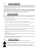
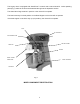
The Legacy mixer is equipped with SmartTimer™ controls and a manual bowl lift. Other operating parts (Fig.1) and their functions are described through out the Operation section. The Guard Wire Cage must be in position or the mixer will not operate. The bowl must stay in locked position on the Bowl Support or the mixer will not operate. If the bowl support is not all the way up (mix position), the mixer will not operate.
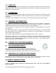
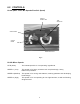
6.2 CONTROLS. HL200 (With Three Mix Speeds Plus Stir Speed) DISPLAY MIXING TIME TIME SELECTOR STOPS MIXER STARTS MIXER SPEED SELECTOR Fig. 2. HL200 Mixer Speeds STIR (Slow) The lowest speed is for incorporating ingredients. SPEED 1 (Low) This speed is for heavy mixtures such as pizza dough, heavy batters and potatoes. SPEED 2 (Medium) This speed is for mixing cake batters, mashing potatoes and developing bread dough.
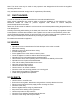
Recipe Timer (Optional) Model HL200 (With Three Mix Speeds Plus Stir Speed) STEPS IN RECIPE PROGRAM SELECT/SAVE DISPLAYS MIXING TIME OR RECIPE # SPEED TIME UP DOWN RECIPE/SPEED SELECTOR OPERATING MODE BUTTONS Fig. 3 The SmartPlus2™ recipe timer has two operating modes, Standard (STD) and RECIPE. Standard Mode Operates exactly as the standard controls utilizing continuous and timed mixing. Recipe Mode • Use mode buttons to switch mixer operation between recipe and standard timed operation.
6.3 BOWL PLACEMENT. The bowl must be installed before the agitator is installed. To install the bowl, lower the bowl support and position bowl so the alignment pins on the left side of the bowl support fit in the holes in the bowl tab. (Fig. 4) Place the slotted tab on bowl into the lower part of the pin. Swing the bowl into the mix position on bowl support. (Fig. 5) Fig. 4 Fig. 5 6.4 AGITATOR. To install an agitator, the bowl must be on the bowl support. To Install 1. Lower the bowl. 2.
6.5 PREPARE FOR MIXING. 1. Place the mixing bowl on the bowl support. 2. Pour ingredients into the bowl. 3. Swing the bowl back to the mix position. 4. Place the agitator inside the bowl, and then attach it to the agitator shaft (Fig. 7). 5. Lift bowl support. 6. Correctly close the bowl guard wire cage. 7. The mixer is now ready for mixing. (See TIMER OPERATION.) Fig. 7 6.6 OPERATING NOTES. • STIR is to be used for incorporating ingredients. Do not use it to develop dough products.
NOTE: If the wire cage is opened at any time, the mixing operation will stop. To resume the mixing operation, close the wire cage and press the START button. 4. Use the STOP button to stop the mixer; the mixing time is displayed in the TIME window. 5. Press the START button to resume mixing if needed. NOTE: When the timer reaches 15:00 minutes, the beeper will sound momentarily and timer will rollover to 00:01 and continue counting until the STOP button is pressed. Fig.
3. When the timer reaches 00:00, the mixer stops; a beeper sounds for 1 second. The countdown timer then displays the last-stored time. RECIPE TIMER OPERATION Fig. 10 Recipe Timer Notes • If pause is selected as a mix speed, the mixer START button must be pressed to advance to the next recipe step after the pause time has expired. • If pause has been selected, the bowl guard can be opened and the time will continue to count down.
View Recipe When the mixer is in RECIPE mode, you can view the step settings of any recipe. 1. Press the SELECT/SAVE button. A. Display will alternate between speed and time. B. The LED of the step being displayed will flash. 2. Use the arrow buttons to view the next step. 3. Use the Recipe selector to view other recipes. 4. Press PGM button to return to the RECIPE mode. NOTE: If the mixer is performing a recipe, the recipe will continue to operate in normal recipe mode sequence.
NOTES: • If a value has been assigned for a step number, that LED will be lit. • The LED for the selected step will blink. • If the default value is still assigned to a step, the LED will not be lit. • When programming, the Recipe and Time Selectors are disabled. SPEED SETTINGS TIME SETTINGS SPd 1 (DEFAULT) 00:00 – 15:00 minutes (10 second increments) SPd 2 End (default) SPd 3 Stir PAUS (pause – no mixing) 5. Use arrows to select step number (1 – 5). 6. Press SPEED.
6.8 UNLOADING. 1. Open the bowl guard wire cage assembly. 2. Lower bowl support. 3. Remove the agitator from the agitator shaft. 4. Slightly lift the bowl off the pin (right side), pull bowl to the front and remove from the bowl support (left side). 6.9 GUARD WIRE CAGE. The bowl guard wire cage can be rotated out of the way to add ingredients or to access the bowl and agitator. Note how the plastic carriers allow the wire cage to ride around the circumference of the planetary drip cup.
6.10 REMOVE AND CLEANING THE GUARD WIRE CAGE. 1. Rotate wire cage to your left until the three carriers align with the carrier escape slots in the circular ridge of the planetary drip cup. 2. Lift the wire cage straight up so the carriers escape from the slots on the drip cup. The bowl guard wire cage can now be removed by pulling toward you. Fig. 14 3. Wash the bowl guard wire cage in a sink, rinse with clear water, and dry with a clean cloth. 4.
6.12 MIXER CAPACITY CHART – HL200 Recommended Maximum Capacities—dough capacities based on 21°C water and 12% flour moisture. PRODUCT AGITATORS SUITABLE FOR OPERATION 20 CAPACITY OF BOWL (LITRE LIQUID) Egg Whites Mashed Potatoes Mayonnaise (Qts. of Oil) Merinque (Qty. of Water) D B&C B or C or D D Waffle or Hot Cake Batter Whipped Cream Cake, Angel Food (8-10 oz. cake) Cake, Box or Slab Cake, Cup Cake, Layer Cake, Pound Cake, Short (Sponge) Cake, Sponge Cookies, Sugar Dough, Bread or Roll § (Lt.-Med.
ABBREVIATIONS - AGITATORS SUITABLE FOR OPERATION B - Flat Beater C - Wing Whip D - Wire Whip ED - Dough Hook I - Wire Whip P - Pastry Knife □1st Speed * 2nd Speed NOTE: %AR (% Absorption Ratio) = Water weight divided by flour weight. Capacity depends on moisture content of dough. Above capacities based on 12% flour moisture at 21°C water temperature. § If high gluten flour is used, reduce above dough batch size by 10%. 2nd speed should never be used on 50% AR or lower Products.
6.13 AGITATORS AND ATTACHMENTS. Hobart Quick Release ™ agitators are available for the Legacy mixers and for the type of product that is being mixed. The B Flat Beater is a multi-purpose agitator used for mashing potatoes or other vegetables, and mixing cakes, batters or icings. It is also used in industrial applications for any product requiring a creaming or rubbing action and uniform dispersion of ingredients. Use first speed for starting most operations; medium speed for finishing.
6.13.1 USING THE ATTACHMENT FACILITY. MEAT CHOPPER ATTACHMENT The Meat Chopper Attachment allows you to prepare many additional foods with your Hobart mixer. A plate having 4-mm holes comes with the Meat Chopper Attachment when shipped from the factory. The maximum allowable hole diameter in the mincing plate is 8 mm and the plate thickness must be greater than 5 mm. If the plate hole diameter is greater than 8 mm an interlocked protective hood is required.
6.15 INSTALLATION AND COMMISSIONING. TOP VIEW BOTTOM VIEW Fig. 15 Overall Dimensions. A 12-litre bowl and agitators are also available. A variety of attachments, agitator and accessories are available. These are described in Section 6.13 (page 21) of this manual.
Table 1. Technical Information.
a) All required safety measures are taken to ensure correct lifting and handling to avoid risk of injury through dropping, falling and tilting. b) No damage occurs to the machine, which could impair the normal operation. 6.17 LOCATION. The mixer is not suitable for outdoor installation and must not be installed where a water jet could be used for cleaning. The mixer must only be operated by trained staff and must be installed in an area where the use and maintenance is restricted to trained personnel.
6.19 OPERATOR TRAINING. Take time to explain the correct operation and cleaning of the Legacy mixer to the users referring to this manual. Leave this manual with the operator and explain that it is important to use it for further reference. 7.0 MIXER MAINTENANCE. A HOBART TRAINED AND COMPETENT PERSON SHOULD CARRY OUT SERVICING. Do not remove any covers or loosen any fittings while the mixer is operating. Ensure the electrical supply has been isolated before attempting to service or move the mixer.
7.1.2 PLANETARY SEAL. Occasionally, the planetary seal (Fig. 18) may become dry and begin to squeak. To correct this, work a little lubrication (mineral oil) under the lip of the seal. Planetary Seal Fig. 18 7.1.3 BOWL LOCKING MECHANISM. Bowl Locking Mechanism should be lubricated after cleaning. Clean only if sticking or hanging up. 7.2 ADJUSTMENTS. 7.2.1 AGITATOR CLEARANCE. The agitator clearance should be checked periodically.
Adjust the Bowl/Agitator Clearance • Remove the apron (which is secured by screws). Stop Screws • Adjust the clearance by loosening the stop screws counterclockwise to increase the clearance or clockwise to decrease the clearance. • After the adjustments are made, replace the apron and secure it with the screws. • Carefully operate the bowl lift several times to check the adjustment. Fig. 19 7.3 INTERLOCK SAFETY SYSTEM.
9.0 RECOMMENDED SPARES. Part Number Description 00-874831 Switch – Speed Selector Assy 00-874809 Knob 00-087714-067-1 Relay (2 Pole, 30 Amp) 00-108197-00001 Screw – Thumb 1.
00-438079 Splash Cover (20 Litre Packaged) 00-874885 Ingredient Chute (Packaged) ML-134299 Mixer Table with Casters 00-874929 Reed Switch w/Fuse 00-916194 Filter and Bracket Assy 00-874761-00005 Motor Drive Assy 00-916197 Motor and Worm Assy 30
10.0 NOTES.
11.0 SERVICE CONTACT NUMBERS. Hobart trained service technicians strategically located throughout the UK are prepared to give you fast, efficient and reliable service. Protect your investment by having a Hobart inspection contract, which assures the continued, efficient operation of your Hobart machines, spares and accessories. For disposal of mixer, contact Hobart Service Centre for return details.
HL200 ML-134311 Page 1 - English Page 33 - Français Page 67 - German INSTALLATION AND OPERATION MANUAL MANUEL D’INSTALLATION ET D’UTILISATION INSTALLATIONS UND BEDIENUNGSANLEITUNG F-34941 (Octobre 2005) 33
Français / Table des matières Section Page Informations sur la sécurité 1.0 36 Directives sur la sécurité 1.1 36 Symboles d’avertissement 1.2 37 Responsabilité 1.3 37 Avant-propos 2.0 37 Informations générales 3.0 37 Prendre soin de votre environnement 4.0 38 Les Matieres D’Emballage 4.1 38 Pour éliminer votre ancien appareil 4.2 38 Instructions de sécurité 5.0 38 Danger provenant de la poussière 5.1 38 Ne jamais 5.
Utilisation du dispositif accessoire 6.13.1 55 Couvercle anti-projections 6.13.2 55 Dispositif racleur du bol 6.13.3 55 Nettoyage 6.14 56 Nettoyage après utilisation 6.14.1 56 Installation et mise en service 6.15 57 Dimensions Fig. 15 57 Informations techniques Tableau 1 58 Déballage et manutention 6.16 58 Localisation 6.17 59 Installation électrique 6.18 59 Formation de l’opérateur 6.19 60 Maintenance du batteur - mélangeur 7.0 60 Lubrification 7.1 60 Glissières 7.
1.0 INFORMATION SUR LA SÉCURITÉ. Les procédures et précautions contenues dans le présent manuel ne s'appliquent qu'à la machine lorsqu'elle est utilisée de la façon prescrite. Si la machine est utilisée autrement que de la façon prescrite, l'opérateur sera responsable de sa propre sécurité et de la sécurité des autres personnes qui peuvent être concernées. Les informations contenues dans le présent manuel ont été préparées pour aider l'opérateur à comprendre, entretenir et utiliser le batteur - mélangeur.
1.2 SYMBOLES D’AVERTISSEMENT. Pour identifier les messages de sécurité dans le présent manuel, les symboles suivants ont été utilisés. Le symbole "Avertissement" se trouve essentiellement lorsque l'information correspondante est importante pour la bonne utilisation de l'appareil en toute sécurité. Le symbole de danger électrique est utilisé lorsqu'il y a des risques de nature électrique. Avant de réviser l'appareil, toujours débrancher le câble d'alimentation électrique du secteur. 1.3 RESPONSABILITÉ.
4.0 PRENDRE SOIN DE VOTRE ENVIRONNEMENT. 4.1 LES MATIÈRES D’EMBALLAGE. La palette et son film d'emballage protecteur en polyéthylène ont été sélectionnés à partir de matières qui respectent l'environnement lors de leur élimination ou qui peuvent être normalement recyclées. Au lieu de les jeter, veuillez vous assurer qu'ils sont recyclés. 4.2 POUR ÉLIMINER VOTRE ANCIEN APPAREIL. Les anciens appareils contiennent des matières qui peuvent être recyclées.
5.2 NE JAMAIS . • • • • • • • • • • • • • • • • Faire fonctionner le batteur - mélangeur ou les accessoires si un défaut apparaît ou si le batteur - mélangeur ne fonctionne pas en sécurité. Porter des vêtements amples. Essayer de mettre la main dans le bol pendant le mélange. Accéder aux pièces tournantes. Monter l'agitateur sur le batteur - mélangeur sans bol en place. Laisser l'agitateur sur l'appareil sans monter le bol. Actionner le batteur - mélangeur avec les accessoires et l'agitateur montés.
• • • • • • • • Ne pas utiliser le batteur - mélangeur ou l'accessoire si un défaut se produit ou si la machine n'est pas sûre. Ne pas accéder aux pièces tournantes. Ne pas utiliser une force excessive en faisant fonctionner l'accessoire, car cela pourrait affecter la stabilité du batteur - mélangeur. Ne pas utiliser le batteur - mélangeur si des pièces sont démontées. Toujours utiliser l'accessoire et / ou le batteur - mélangeur dans une zone bien éclairée.
FENTE COMMANDES PRISE D’ACCESSOIRES PROTECTION ANTIPROJECTIONS GODET À GOUTTES TABLIER CAGE MÉTALLIQUE DE PROTECTION DU BOL SUPPORT DU BOL AGITATEUR Figure 1.
6.2 COMMANDES. HL200 (Avec trois vitesses de mixages Plus une vitesse d’agitation) AFFICHAGE TEMPS DE MIXAGE SÉLECTEUR DE DURÉE ARRÊT DU MIXEUR DÉMARRAGE DU BATTEUR MÉLANGEUR SÉLECTEUR DE VITESSE Figure 2. Vitesses du batteur - mélangeur HL200 STIR (BRASSAGE) (Lent) La vitesse la plus lente, conçue pour l’incorporation des ingrédients. VITESSE 1 (Lent) Cette vitesse convient pour les mélanges lourds tels que la pâte à pizza, les pâtes liquides lourdes et les pommes de terre.
Minuteur recette (facultatif) Modèle HL200 (Avec trois vitesses de mixages Plus une vitesse d’agitation) AFFICHE LE TEMPS DE MIXAGE DE LA RECETTE PROGRAMME ÉTAPES DE LA RECETTE SÉLECTIONNER/SAUVEGARDER VITESSE TEMPS PLUS MOINS SÉLECTEUR DE RECETTE/ VITESSES BOUTONS MODE DE FONCTIONNEMENT Fig. 3 Le minuteur de recette SmartPlus2™ possède deux modes de fonctionnement. Le mode standard (STD) et le mode recette (RECIPE).
6.3 POSITIONNEMENT DU BOL. Le bol doit être installé avant d'installer l'agitateur. Pour installer le bol, abaisser le support du bol et positionner le bol de façon à ce que les broches d'alignement du côté gauche du support de bol s'adaptent dans les languettes du bol (Figure 4). Placer la languette fendue du bol dans la partie inférieure de la broche. Basculer le bol en position de mixage sur le support de bol (Figure 5). Figure 4 Figure 5 6.4 AGITATEUR.
6.5 PRÉPARATION POUR LE MIXAGE. 1. Placer le bol de mixage sur le support du bol. 2. Verser les ingrédients dans le bol. 3. Basculer le bol à nouveau dans la position de mixage. 4. Placer l'agitateur à l'intérieur du bol, puis le fixer à l'arbre de l'agitateur (Figure 7). 5. Relever le support du bol. 6. Fermer correctement le panier métallique de protection du bol. 7. Le mixeur est maintenant prêt pour le mixage (voir FONCTIONNEMENT DE LA MINUTERIE). Figure 7 6.6 NOTES POUR L’UTILISATION.
2. Mettre le temporisateur sur HOLD (Maintien) en tournant le sélecteur TIME (Temps) dans le sens anti-horaire jusqu'à ce que la mention "HOLD" (Maintien) apparaisse sur la fenêtre de TEMPS. 3. Appuyer sur le bouton START (Démarrage) pour commencer le mixage. Le temporisateur commence à compter à partir de 00:00. NB : Si l'on ouvre le panier métallique à tout moment, l'opération de mélange s'arrête.
nouveau temps remplacera les 30 secondes initiales pour SPEED 1 après qu'on ait appuyé sur le bouton START. c. Si l'on change le temps pendant le mixage, le batteur - mélangeur fonctionnera jusqu'à ce que le nouveau temps expire. Le réglage du temps ne sera pas mémorisé. d. Si l'on change la vitesse pendant le mixage, le temps passera au temps précédent pour la vitesse sélectionnée et comptage à rebours. NB : Si l'on ouvre le panier métallique à tout moment, l'opération de mixage s'arrête.
a. La vitesse est affichée pendant quelques instants. b. Le temps restant pour l’étape en cours s’affiche et l’indicateur d’étape s’allume. NB: Les boutons “RECIPE” (Recette) et “TIME” (Temps) sont désactivé. 4. Le batteur - mélangeur va continuer à fonctionner à la vitesse et au temps programmés jusqu’à ce que les étapes de la recette soient achevées.
1. Si un temps de mixage est affiché, appuyer sur le bouton de mode RECIPE (Recette). L’affichage correspond avec le sélecteur de position de recette (vitesse). 2. Appuyer et maintenir le bouton TIME (Temps). Continuer à maintenir TIME, et appuyer ensuite sur PGM et maintenir jusqu’à ce que “rP1” s’affiche (et l’indicateur d’étape 1 clignote), la sonnerie retentit et les LED du programme s’allument. 3. Utiliser les flèches pour sélectionner le numéro de recette (1 – 4) à programmer. 4.
NB: Si les 5 étapes sont programmées, la recette va se terminer à la fin de l’étape 5. S’il y a moins de 5 étapes, le réglage du temps par défaut END (Fin) terminera la recette. B. Appuyer sur SELECT/SAVE (Sélectionner/Sauvegarder) pour régler le temps pour l’étape. “SAVE” va s’afficher durant quelques instants et la sonnerie va retentir. 9. L’affichage alterne entre la vitesse et le temps pour indiquer le mode de programmation. NB: La LED de l’étape programmée va clignoter. 10.
Figure 12 Figure 13 6.10 RETIRER ET NETTOYER LE PANIER MÉTALLIQUE DE PROTECTION. 1. Faire tourner le panier métallique sur la gauche jusqu’à ce que les trois supports s’alignent avec les fentes d’évacuation du support sur le bord circulaire de la coupelle planétaire d’égouttement. 2. Lever le panier métallique de manière verticale pour que les supports se retirent des fentes sur la coupelle d’égouttement. Vous pouvez maintenant retirer le panier métallique de protection du bol peut en tirant vers vous.
6.11 RÉ-ASSEMBLAGE DU PANIER MÉTALLIQUE DE PROTECTION. 1. Positionner la bague du panier métallique de protection du bol de façon à ce que les supports soient placés au-dessus des fentes dans la coupelle d’égouttement planétaire. 2. Abaisser le panier métallique de protection du bol de façon à ce que les supports passent à travers les fentes. 3. Faire tourner le panier métallique de protection du bol sur la droite jusqu’à ce qu’il s’arrête, en position fermée. 6.
Gâteau éponge C ou I 5,4 kg (12 livres.) Cookies, sucré B 6,8 kg (15 livres.) Pâte à pain ou petits pains (léger à moyen) 60 % de TA § ED 11,3 kg (25 livres.)□ 5,9 kg (13 livres.)□ ED 6,8 kg (15 livres.)□ B&P 8,2 kg (18 livres.) 3,6 kg (8 livres.)□ 5 kg (11 livres.) ED 4,1 kg (9 livres.)□ Pâte à pizza moyenne 50 % TA § ED 4,5 kg (10 livres.)□ Pâte à pizza épaisse 60 % TA § Pâte à beignet levée 65% TA § ED 9,1 kg (20 livres.)□ 2,3 kg (5 livres.)□ 2,7 kg (6 livres.)□ 5 kg (11 livres.
6.13 AGITATEURS ET ACCESSOIRES. Les agitateurs Hobart Quick Release ™ sont disponibles pour les mixeurs Legacy et pour le type de produit qui est mixé. Le Mixeur Plat B est un agitateur à usages multiples qui est utilisé pour écraser les pommes de terre et autres légumes et mélanger les gâteaux, pâte à crêpes ou glaçages. Il est également utilisé dans les applications industrielles pour tous produits exigeant une action de crémage ou frottage et une dispersion uniforme des ingrédients.
6.13.1 UTILISATION DU DISPOSITIF ACCESSOIRE. DISPOSITIF POUR HACHER LA VIANDE Le dispositif de hachage de la viande permet de préparer de nombreux aliments supplémentaires avec le batteur - mélangeur Hobart. Le dispositif de hachage de la viande est livré avec un plateau à trous de 4 mm lorsqu'il est expédié de l'usine. D'autres plateaux sont disponibles avec des trous de 2, 5, 6, 10, 13, 16 et 18 mm pour hachage fin à grossier.
6.14 NETTOYAGE. NETTOYAGE DES NOUVEAUX BOLS ET ACCESSOIRES DU BATTEUR MÉLANGEUR Avant la première utilisation, bien laver les nouveaux bols et agitateurs du batteur mélangeur (mixeurs, fouets, crochets à pâte et couteaux à pâte). Laver à l'eau chaude et une solution de détergent doux, en rinçant avec une solution de carbonate de soude peu forte ou de vinaigre et bien rincer à l'eau claire.
6.15 INSTALLATION ET MISE EN SERVICE. CENTRE DE GRAVITÉ CABLE D’ALIMENTATION STANDARD 1.8 M TROUS DE FIXATION 3/8 – 16 FILETRAGE UNC 4 EMPLACEMENTS PIVOT R 390 (15 – 3/8) VUE DE DESSUS VUE D’ENDESSOUS Fig. 15 Dimensions hors tout. Un bol de 12 litres et des agitateurs sont également disponibles. Divers accessoires, agitateurs et autres pièces sont disponibles. Ils sont décrits dans la Section 6.13 (page 54) du présent manuel.
Tableau 1. Informations Techniques.
en utilisant la fourche d'un chariot élévateur par l'arrière de l'unité. Lorsqu'on déplace l'unité, toujours enfourcher par l'arrière de l'unité. Pendant cette opération, veiller à s'assurer que: a) Toutes les mesures de sécurité requises ont été prises pour assurer le levage et la manutention corrects afin d'éviter tous risques de blessures par suite de chute, et basculement. b) Aucun dommage ne se produit pour la machine, ce qui pourrait nuire au fonctionnement normal. 6.17 LOCALISATION.
6.19 FORMATION DE L’OPÉRATEUR. Prendre soin d'expliquer le bon fonctionnement et nettoyage du batteur - mélangeur Legacy aux opérateurs, en se référant au présent manuel. Confier ce manuel à l'opérateur et expliquer qu'il est important de l'utiliser pour référence ultérieure. 7.0 MAINTENANCE DU BATTEUR - MÉLANGEUR. UNE PERSONNE COMPÉTENTE ET FORMÉE PAR HOBART DOIT EFFECTUER LA RÉVISION. Ne retirer aucun couvercle ni desserrer aucune pièce tant que le batteur - mélangeur est en fonctionnement.
7.1.2 JOINT PLANÉTAIRE. Occasionnellement, le joint planétaire (Figure 18) peut devenir sec et commencer à grincer. Pour corriger cela, introduire une petite quantité d'huile de lubrification (huile minérale) sous la lèvre du joint. Joint planétaire Figure 18 7.1.3 MÉCANISME DE BLOCAGE DU BOL. Le mécanisme de verrouillage du bol doit être lubrifié après nettoyage. Ne nettoyer que s'il est grippé ou immobilisé. 7.2 RÉGLAGES. 7.2.1 DÉGAGEMENT DE L’AGITATEUR.
Ajuster le dégagement bol / agitateur • Retirer le tablier (qui est fixé par des vis à tête fendue). Vis d’arrêt • Ajuster le dégagement en desserrant les vis de butée dans le sens inverse des aiguilles d’une montre afin d’augmenter le dégagement ou dans le sens des aiguilles d’une montre pour diminuer le dégagement. • Après avoir effectué les réglages, re-placer le tablier et le fixer à l'aide des vis.
9.0 PIÈCES DE RECHANGE RECOMMANDÉES. Numéro de pièce Description 00-874831 Interrupteur – Ensemble de sélecteur de vitesse 00-874809 Bouton 00-087714-067-1 Relais (2 pôles, 30 A) 00-108197-00001 Vis à serrage à main 1.
00-438079 Couvercle anti-projections (Pack 20 litres) 00-874885 Goulotte pour ingrédients (incluse dans le pack) ML-134299 Table de mixage avec roulettes 00-874929 Contact en ampoule avec fusible 00-916194 Assemblage filtre et support 00-874761-00005 Assemblage entrînement par moteur 00-916197 Assemblage moteur et vis sans fin 64
10.0 NOTES.
11.0 NUMÉROS DE CONTACT POUR LE SERVICE APRÈSVENTE. Des techniciens d'entretien formés par Hobart et situés stratégiquement au France sont prêts à vous donner un service fiable, rapide et efficace. Protégez votre investissement en passant un contrat d'inspection Hobart, qui assure le fonctionnement continu et efficace de vos appareils, pièces de rechange et accessoires Hobart. Pour éliminer le batteur - mélangeur, contacter le centre de service après-vente Hobart pour tous renseignements sur le retour.
HL200 ML-134311 Seite 1 - Englisch Seite 33 - Französisch Seite 67 - Deutsch INSTALLATION AND OPERATION MANUAL MANUEL D’INSTALLATION ET D’UTILISATION INSTALLATIONS- UND BEDIENUNGSANLEITUNG F-34941 (Oktober 2005) 67
Deutsch / Inhalt Kapitel Seite Sicherheitsinformation 1.0 70 Sicherheitsrichtlinien 1.1 70 Warnsymbole 1.2 71 Haftung 1.3 71 Vorwort 2.0 71 Allgemeine Informationen 3.0 71 Umweltschutz Verpackungsmaterial 4.0 72 4.1 72 Entsorgung Ihres Altgerätes 4.2 72 Sicherheitshinweise 5.0 72 Staubgefahr 5.1 72 Was Sie niemals tun sollten 5.2 73 Was Sie immer beachten sollten 5.3 73 Sicherheitshinweise zum Zubehör 5.4 73 Inbetriebnahme und Bedienung 6.
Rührleistung 6.12 86 Rührwerkzeuge und Zubehör 6.13 88 Verwendung der Zusatzfunktionen 6.13.1 89 Spritzschutz 6.13.2 89 Kesselschaber 6.13.3 89 Reinigung 6.14 89 Reinigung nach Gebrauch 6.14.1 89 Installierung und Inbetriebnahme 6.15 90 Gesamtabmessungen Abb. 15 90 Technische Daten Tabelle 1 91 Auspacken 6.16 92 Standort 6.17 92 Elektrische Installation 6.18 93 Anwendertraining 6.19 93 Wartung der Rührmaschine 7.0 93 Schmierung 7.1 93 Gleitbahnen 7.1.
1.0 SICHERHEITSINFORMATIONEN. Die in der Bedienungsanleitung beschriebenen Vorgänge und Sicherheitsmaßnahmen beziehen sich nur auf die hier genannte Verwendung des Gerätes. Sollte das Gerät entgegen der empfohlenen Weise benutzt werden, so ist der Benutzer für seine/ihre eigene sowie für die Sicherheit anderer beteiligter Personen verantwortlich. Die Informationen in dieser Bedienungsanleitung dienen dazu, dem Benutzer die Bedienung sowie die Instandhaltung der Rührmaschine zu erklären.
1.2 WARNSYMBOLE. Zur Kennzeichnung der Sicherheitshinweise in dieser Bedienungsanleitung werden die folgenden Symbole verwendet: Das Warnsymbol weist auf einen wichtigen Hinweis zur sicheren Anwendung des Gerätes hin. Das Elektrizitätszeichen weist auf Risiken hin, die durch Elektrizität entstehen. Ziehen Sie vor Wartung des Gerätes unbedingt den Netzstecker. 1.3 HAFTUNG. Installationen und Reparaturen dürfen nur von qualifiziertem Fachpersonal durchgeführt werden. Verwenden Sie nur Originalersatzteile.
4.0 UMWELTSCHUTZ. 4.1 VERPACKUNGSMATERIAL. Die Palette und die schützende Polyethylenverpackungsfolie sind aus umweltfreundlichem, recycelfähigem Material. Werfen Sie das Verpackungsmaterial bitte nicht weg, sondern sorgen Sie dafür, dass es recycelt wird. 4.2 ENTSORGUNG IHRES ALTGERÄTES. Altgeräte enthalten Materialien, die recycelt werden können. Bitte fragen Sie bei Ihrer Müllsammelstelle (z.B.
5.2 WAS SIE NIEMALS TUN SOLLTEN. • • • • • • • • • • • • • • • • Die Rührmaschine oder das Zubehör benutzen, wenn ein Fehler aufgetreten oder die Rührmaschine beschädigt worden ist. Lockere Kleidung tragen. Versuchen in den Kessel zu greifen, wenn der Mixer in Betrieb ist. Nach den rotierenden Elementen greifen. Das Rührwerkzeug an der Rührmaschine befestigen, wenn kein Kessel angebracht ist. Das Rührwerkzeug an der Rührmaschine lassen, ohne den Kessel angebracht zu haben.
DAS ZUBEHÖR UND/ODER DIE MASCHINE DARF NUR VON EINER QUALIFIZIERTEN UND GESCHULTEN PERSON BENUTZT WERDEN. • • • • • • • • • • Bringen Sie kein Zubehör an, wenn die Rührmaschine in Betrieb ist. Tragen Sie keine lockere Kleidung. Benutzen Sie die Rührmaschine oder Zubehör nicht, wenn ein Fehler aufgetreten oder die Rührmaschine beschädigt ist. Greifen Sie nicht nach den rotierenden Elementen. Üben Sie keinen übermäßigen Druck aus, wenn Sie die Rührmaschine benutzen.
Der Kessel muss sich in verriegelter Stellung in der Kesselhalterung befinden, damit die Rührmaschine funktioniert. Wenn sich die Kesselhalterung nicht in der Mixposition befindet, startet die Rührmaschine nicht. SCHLITZ BEDIENUNGSELEMENTE ANSCHLUSSDOSE FÜR DAS ZUBEHOER SPRITZSCHUTZ VORRICHTUNG ZUM SPRITZSCHUTZ UND AUFFANGSCHALE STAHLSCHUTZ SCHUTZDRAHTKORB KESSELHALTERUNG RUEHRWERK Abb.
6.2 BEDIENUNGSELEMENTE. Modell HL200 (Mit drei verschiedenen Mixstufen und einer Rührstufe) ZEIGT DIE GEWÄHLTE MIXGESCHWINDIGKEIT AN SCHALTER ZUM AUSWÄHLEN DER ZEIT HÄLT DIE RÜHRMASCHINE AN STARTET DIE RÜHRMASCHINE SCHALTER ZUM AUSWAEHLEN DER GESCHWINDIGKEIT Abb. 2. HL200 Mixstufen RÜHREN (Langsam) Mit der kleinsten Stufe können Sie die Zutaten am Anfang des Mixvorgangs nach und nach hinzugeben. STUFE 1 (Niedrig) Diese Stufe eignet sich zum Vermischen von schweren Zutaten wie z.B.
Programmierbarer Timer (Optional) Modell HL200 (Mit drei Mixstufen und Rührgeschwindigkeit) STUFEN IM PROGRAMM PROGRAMMIEREN AUSWAEHLEN/SPEICHERN ZEIGT MIXZEIT ODER PROGRAMMAN GESCHWINDIGKEIT ZEIT HOCH RUNTER SCHALTER ZUM AUSWAEHLEN DES PROGRAMMS/ DER GESCHWINDIGKEIT TASTEN FUER BETRIEBSMODUS Abb. 3 Der SmartPlus2™ Programmtimer hat zwei Betriebsstufen, Standard (STD) and PROGRAMM. Standardmodus Arbeitet genauso wie die Standardbedienungselemente, das fortlaufende und zeitlich festgelegte Mixen.
6.3 POSITIONIERUNG DES KESSELS. Der Kessel muss vor dem Rührwerkzeug installiert werden. Senken Sie die Kesselhalterung, um den Kessel anzubringen. Positionieren Sie den Kessel so, dass die Zentrierstifte auf der linken Seite der Halterung in die Löcher der Kesselhalterung passen (Abb. 4). Führen Sie die gespaltene Halterung auf dem Kessel in den unteren Teil des Stiftes. Lassen Sie den Kessel in der Rührposition in der Halterung einrasten. (Abb. 5) Abb. 4 Abb. 5 6.4 RÜHRWERKZEUGE.
6.5 VOR DEM MIXEN. 1. 2. 3. 4. Setzen Sie den Rührkessel in die Kesselhalterung ein. Geben Sie die Zutaten in den Kessel. Lassen Sie den Kessel wieder in der Kesselhalterung einrasten. Platzieren Sie das Rührwerkzeug so, dass er sich innerhalb des Kessels befindet und befestigen Sie ihn dann an der Rührwelle (Abb. 7). 5. Heben Sie die Kesselhalterung an. Abb. 7 6. Schließen Sie den Schutzdrahtkorb des Kessels wieder. 7. Nun können Sie die Rührmaschine zum Mixen benutzen. (Siehe TIMERBETRIEB) 6.
2. Halten Sie den Zeitwähler an, indem Sie den Schalter so lange entgegen dem Uhrzeigersinn drehen, bis “HOLD” aufleuchtet. 3. Drücken Sie die START-Taste, um den Mixvorgang zu starten. Der Timer beginnt nun von 00:00 an zu zählen. BEACHTEN SIE: Wird der Drahtkorb geöffnet, so wird der Mixvorgang automatisch angehalten. Um diesen weiterlaufen zu lassen, schließen Sie bitte den Drahtkorb und drücken Sie erneut die START-Taste. 4.
Diese neue Einstellung ersetzt die zuvor gewählten 30 Geschwindigkeitsstufe 1, nachdem die START-Taste betätigt wurde. Sekunden bei c. Wenn die Zeiteinstellung während des Mixvorgangs verändert worden ist, dann wird die Rührmaschine so lange in Betrieb sein, bis die neue Zeitdauer abgelaufen ist. Die neue Zeiteinstellung wird nicht gespeichert. d. Wenn die Geschwindigkeit während des Mixvorgangs verändert worden ist, dann verändert sich auch die Zeiteinstellung.
3. Drücken Sie START: Die Rührmaschine wird nun in der eingestellten Geschwindigkeit mit der eingestellte Zeit laufen. a. Die Geschwindigkeit wird kurz angezeigt. b. Die verbleibende Zeit für die laufende Stufe wird angezeigt und die Lampe für die Stufe leuchtet auf. BEACHTEN SIE: Programm- und Zeitwähler werden deaktiviert. 4. Die Rührmaschine läuft mit der eingestellten Geschwindigkeit und Zeit, bis die einzelnen Programmstufen beendet sind.
1. Wenn die Mixzeit angezeigt wird, drücken Sie die Taste RECIPE (Programm) Modus. Das Display zeigt die Programm- (Geschwindigkeits-) wahl an. 2. Halten Sie die Taste TIME gedrückt. Halten Sie TIME weiter gedrückt, drücken Sie dann PGM und halten Sie diese, bis rP1 angezeigt wird (und Step 1 blinkt), der Signalgeber ertönt und die LEDs für die eingestellten Stufen aufleuchten. 3. Benutzen Sie die Pfeiltasten, um die Programmnummer (1-4) zum Einstellen auszuwählen. 4.
BEACHTEN SIE: Wenn alle 5 Stufen eingestellt worden sind, endet das Programm nach Abschluss der 5. Stufe. Wenn weniger als 5 Stufen verwendet werden, wird die vorgegebene Zeiteinstellung von END das Programm beenden. B. Drücken Sie SELECT/SAVE, um die Zeit für die Stufe auszuwählen. SAVE wird kurz angezeigt und der Signalgeber ertönt. 9. Das Display zeigt abwechselnd die Geschwindigkeit und die Zeit an, um den ProgrammModus anzugeben. BEACHTEN SIE: LED der eingestellten Stufe leuchtet auf. 10.
Abb.12 Abb. 13 6.10 ENTFERNEN UND REINIGEN DES SCHUTZDRAHTKORBES. 1. Drehen Sie den Drahtkorb nach links, bis die drei Halterungen sich nach den Halterungsschlitzen in der runden Einfassung der kreisförmigen Auffangschale ausrichten. 2. Heben Sie den Drahtkorb geradlinig nach oben, so dass die Halterungen sich aus den Schlitzen an der Auffangschale lösen können. Sie können nun den Schutzdrahtkorb des Kessels entfernen, indem Sie sie ihn zu sich gewandt herausnehmen. Abb. 14 3.
6.11 EINSETZEN DES SCHUTZDRAHTKORBES. 1. Platzieren Sie den Ring des Schutzdrahtkorbes so, dass sich die Halterungen über den Schlitzen der kreisförmigen Auffangschale befindet. 2. Senken Sie den Schutzdrahtkorb so, dass die Halterungen durch die Schlitze passen. 3. Drehen Sie den Schutzdrahtkorb nach rechts, bis er an der Stopp- und geschlossenen Position einrastet. 6.
Teig für hohen Donut 65% Absorption Teig, Vollkornteig 70% Absorption Eier & Zucker für Rührkuchen Zuckerguss, Fondant Zuckerguss, Marshmallow Backfett & Zucker, mit Sahne Pasta,Einfache Eiernudeln (max. Rührzeit 5 Min.) ABKÜRZUNGEN FÜR BETRIEB GEEIGNETE RÜHRER B - Standardrührer C - Flügelbesen D - Schneebesen ED - Knethaken I – Schneebesen P - Gebäcksschneider _1. Stufe * 2. Stufe ED 4,1 kg 1,8 kg ED 9,1 kg 5 kg B & C oder I B C oder I 36 kg 5.
6.13 RÜHRWERKZEUGE UND ZUBEHÖR. Hobart Quick Release ™ Rührwerkzeuge sind für die Legacy Rührmaschinen und das zu rührende Produkt erhältlich. Der Standardrührer B ist ein Mehrzweckrührer zum Stampfen von Kartoffeln und anderem Gemüse, zum Rühren von Kuchenteig, Backteig oder Zuckerguss. Er eignet sich auch für industrielle Anwendungen bei zu schäumenden oder geriebenen Produkten und eine gleichmäßige Verteilung der Zutaten.
6.13.1 VERWENDUNG DER ZUSATZFUNKTIONEN. FLEISCHWOLFZUSATZ Mit dem Fleischwolfzusatz können Sie viele weitere Lebensmittel mit Ihrer Hobart Rührmaschine zubereiten. Mit dem Fleischwolfzusatz wird eine Platte mit 4mm-Löchern mitgeliefert. Andere Platten sind in den Lochgrößen 2, 5, 6, 10, 13, 16 und 18 mm für grobe bis feine Ergebnisse erhältlich. Die Ergebnisse entsprechen denen der Hobart Fleischwölfe für den industriellen Gebrauch. Verwenden Sie den Fleischwolfzusatz beim HL200 in der dritten Stufe.
Beachten Sie bitte, dass Rührwerkzeuge aus Aluminium nicht für den Geschirrspüler geeignet sind. 6.15 INSTALLATION UND INBETRIEBNAHME. ZENTRUM DER SCHWERKRAFT 6 FT/1.8 M StandardSpannungsversorgungskabel Anschraubbohrungen 3-8/16 Unc Gewinde 4 Stellen R 390 (15-3/8”) Schwenkvorrichtung Ansicht von oben Ansicht von unten Abb.
GESAMTABMESSUNGEN. Ein 12 Liter-Kessel und Rührwerkzeuge sind ebenfalls erhältlich. Eine Auswahl an Zubehör, Rührwerkzeugen und Zubehör sind erhältlich. Diese werden in Kapitel 6.13 (Seite 88) dieser Bedienungsanleitung beschrieben. Tabelle 1. Technische Daten. Beschreibung Einheit Leistung der Rührmaschine Höchstdrehzahl (50Hz) Nennspannung 1 ph Volllaststrom bei Spannung..............................................3ph Anzugsstrom bei o.
6.16 AUSPACKEN UND BEDIENUNG. Um Beschädigungen zu vermeiden sollte die Rührmaschine nach Möglichkeit immer in der Verpackung bis zu ihrem endgültigen Standort transportiert werden. Verwenden Sie zum Öffnen der Box keine scharfen Gegenstände, da Sie sons das Gerät beschädigen könnten. Überprüfen Sie das Gerät auf mögliche Transportschäden. Im Falle einer Beschädigung des Gerätes bewahren Sie die Originalverpackung auf und kontaktieren Sie Ihren nächsten Hobart Händler.
6.18 ELEKTRISCHE INSTALLATION. Die elektrische Installation der Rührmaschine Mixers muss den geltenden Vorschriften der örtlichen Energieversorgungsunternehmen entsprechen. A Die elektrisDie elektrische Installation muss von qualifiziertem Fachpersonal durchgeführt werden. Die elektrischen Voraussetzungen für die verschiedenen Rührmaschinenoptionen werden in Tabelle 1, Seite 91 aufgeführt. Prüfen Sie vor dem Anschluss, dass die Stromversorgung mit den Angaben auf der Maschine übereinstimmt.
Gleitbahn. Setzen Sie den Stahlschutz wieder ein und schrauben Sie ihn fest. Die Artikelnummer für das Lubriplate Öl finden Sie im Kapitel ‚Empfohlene Ersatzteile’. Gleitbahn Sensorhalter Halterung Schraube Stahlsc Abb. 16 Abb. 17 BEACHTEN SIE: Entfernen Sie nicht die Schrauben des Sensorhalters, um den Stahlschutz zu entfernen. 7.1.2 UMLAUFDICHTUNG. Gelegentlich wird die Umlaufdichtung (Abb. 18) trocken und fängt zu quietschen an.
7.2 JUSTIERUNG. 7.2.1 REICHWEITE DER RÜHRWERKZEUGE. Die Reichweite der Rührwerkzeuge sollte regelmäßig kontrolliert werden. Das Rührwerkzeug sollte den Kessel nicht berühren und der maximale Abstand zwischen dem Kesselboden und dem Standardrührer B sollte 3mm betragen; der maximale Abstand zwischen dem Kesselboden und dem ED Knethaken sollte 8 mm betragen. Setzen Sie einen Kessel und ein Rührwerkzeug (z.B. einen Standardrührer) ein.
8.0 FEHLERSUCHE. Problem Mögliche Ursachen Das Rührgerät startet nicht. Zeitanzeige leuchtet auf – siehe unten Der Schaltkreisschutz ist geöffnet – kontrollieren Sie die Sicherung oder den Leitungsschutzschalter. Die Rührmaschine ist überladen. Der Drahtkorb ist nicht geschlossen. Der Kessel ist nicht geschlossen (in Rührstellung) oder der Kessel befindet sich nicht in der oberen Stellung ist. Rührwerkzeuge berühren den Kessel. Der Kessel ist nicht geschlossen (in Rührstellung).
9.0 EMPFOHLENE ERSATZTEILE. Artikelnummer Beschreibung 00-874831 Schalter - Geschwindigkeitswähler 00-874809 Drehknopf 00-087714-067-1 Relais (2 Pole, 30 Amp) 00-108197-00001 Fingerschraube – 1,125 00-291221 Schnecke – Getriebe 60 Zyklus 00-874816 Halterung - Drahtkorb 00-874816-00002 Halterung – Drahtkorb (gespalten) 00-874816 Halterung - Drahtkorb 00-874875 Magnet - Platte 00-874822 Drahtkorb 00-874815 Spritzschutz 00-874832 Auffangschale & Flanschbecher 00-874864 Kessel (12 Qt.
00-438079 Spritzschutz (20 Qt.
10.0 NOTIZEN.
11.0 TECHNISCHER SERVICE - KONTAKTDATEN. Hobart bietet Ihnen technische Unterstützung durch unsere geschulten Techniker in unseren nationalen Hobart-Servicezentralen, die Ihnen schnell, effizient und zuverlässig helfen. Für eine lange Lebensdauer Ihres Gerätes empfehlen wir Ihnen den Abschluss eines Wartungsvertrages mit Hobart, damit Ihre Hobart Geräte, Ersatz- und Zubehörteile auch in Zukunft einwandfrei funktionieren.