HL200 MIXER TECHNICAL MANUAL SPECIFICATION SHEET INSTALLATION INSTRUCTIONS OPERATION INSTRUCTIONS CLEANING INSTRUCTIONS MAINTENANCE INSTRUCTIONS TROUBLE SHOOTING INSTRUCTIONS WIRING DIAGRAMS CATALOG OF REPLACEMENT PARTS SMARTPARTS™ USER GUIDE RECOMMENDED SPARE PARTS LIST
Need other Hobart Services? • Warranty Registration • Delivery and Installation • Preventive Maintenance • Hobart Service Contracts • Extended Warranty Contracts • Parts and Accessories • Specialty Programs • Water Treatment Programs HL200 Mixer Technical Manual Page 2 of 111
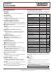
Item #______________________________________ Quantity____________________________________ C.S.I. Section 11400 LEGACY® HL200 MIXER 701 S Ridge Avenue, Troy, OH 45374 1-888-4HOBART • www.hobartcorp.com STANDARD FEATURES MODELS ■ Heavy-Duty 1⁄2 H.P.
LEGACY® HL200 MIXER 701 S Ridge Avenue, Troy, OH 45374 1-888-4HOBART • www.hobartcorp.com SOLUTIONS/BENEFITS HL200 MIXER CAPACITY CHART ⁄2 H.P.
LEGACY® HL200 MIXER 701 S Ridge Avenue, Troy, OH 45374 1-888-4HOBART • www.hobartcorp.com SPECIFICATIONS MOTOR: 1 ⁄2 H.P. high torque motor. 100-120/50/60/1 200-240/50/60/1 BOWL LIFT: Ergonomic style, hand crank operated, self-locking in top and bottom position. 8.0 Amps 5.0 Amps ELECTRICAL: 100-120/50/60/1, 200-240/50/60/1 – UL Listed. CONTROLS: Magnetic contactor with thermal overload protection. Internally sealed “Start-Stop” push buttons. A 15-minute SmartTimer™ is standard.
LEGACY® HL200 MIXER 701 S Ridge Avenue, Troy, OH 45374 1-888-4HOBART • www.hobartcorp.com SPECIFICATIONS ELECTRICAL SPECIFICATIONS: 100-120/50/60/1, 200-240/50/60/1 – UL Listed. WEIGHT: 189 lbs. net; 204 lbs. domestic shipping. WARRANTY: Unit has full one-year warranty on parts, labor and mileage against manufacturer’s defects. Service contracts are available. DETAILS AND DIMENSIONS As continued product improvement is a policy of Hobart, specifications are subject to change without notice.
Models HL120 HL200 HL200 HL 200 HL200 ML-134296 ML-134459 ML-134331 ML-134458 ML-134289 ML-134457 ML134455 ML-134450 PRIOR ML’S COVERED IN TH IS MANUAL PRIOR ML’S COVERED IN THIS HL200 HL200 HL200 ML-134308 CATALOG ML-134308 ML-134450 INSTRUCTION MANUAL 701 S. RIDGE AVENUE TROY, OHIO 45374 -0001 937-332-3000 · W W W.HOBARTCORP.COM F34922 Rev. C (Sept.2008) F34922 Rev. D (Nov.
TABLE OF CONTENTS GENERAL ............................................................................................... 3 INSTALLATION............................................................................................... 3 Unpacking .............................................................................................3 Location ................................................................................................3 Electrical Connections ...........................................
Installation, Operation and Care of LegacyTM 12 & 20-Quart Mixers SAVE THESE INSTRUCTIONS GENERAL The Legacy 12-quart mixer is a bench-type mixer which features a SmartTimer™, a manual bowl lift and a #12 attachment hub as standard equipment. The Legacy 20-quart mixer is a bench-type mixer which features a SmartTimer™, a manual bowl lift and a #12 attachment hub as standard equipment. With the use of special agitators, a 12 quart bowl may be used on the HL200 mixer.
ELECTRICAL CONNECTIONS (Cord Connected Mixers) The electrical cord on this machine is equipped with a three-pronged grounding plug which must be connected to a properly grounded receptacle. If the ELECTRICAL CONNECTIONS (Cord Connected Mixers) receptacle is not the proper grounding type, contact an electrician. Do Not remove the WARNING:prong THE ELECTRICAL CORD ON THIS MACHINE IS EQUIPPED WITH A THREEgrounding from the plug. PRONGED GROUNDING PLUG WHICH MUST BE CONNECTED TO A PROPERLY GROUNDED RECEPTACLE.
OPERATION OPERATION Moving agitator in bowl. Keep hands, clothing, and utensils out of bowl WARNING: MOVING AGITATOR IN BOWL. KEEP HANDS, CLOTHING, AND UTENSILS OUT operation. Do Not use without interlocked guard. OF BOWL WHILE IN OPERATION. DO NOT USE WITHOUT INTERLOCKED GUARD. The Legacy mixer is equipped with SmartTimerTM controls. Refer to Fig. 1 for operating parts and OPERATION section for their functions. The bowl guard wire cage must be in closed position or the mixer will not operate.
Standard Controls Models HL120/HL200 (With Three Mix Speeds Plus Stir Speed) DISPLAY MIXING TIME STOPS MIXER TIME SELECTOR STARTS MIXER SPEED SELECTOR Fig. 2 HL120/HL200 Mixer Speeds STIR (Slow) The lowest speed is for incorporating ingredients. SPEED 1 (Low) This speed is for heavy mixtures such as pizza dough, heavy batters and potatoes. SPEED 2 (Medium) This speed is for mixing cake batters, mashing potatoes and developing bread dough.
Recipe Timer (Optional) Models HL120/HL200 (With Three Mix Speeds Plus Stir Speed) Fig. 15 The SmartPlus2 ™ recipe timer has two operating modes, Standard (STD) and RECIPE. Standard Mode Operates exactly as the standard controls utilizing continuous and timed mixing. Recipe Mode x Use mode buttons to switch mixer operation between recipe and standard timed operation.
BOWL PLACEMENT The bowl must be installed before the agitator is installed. To install the bowl, lower the bowl support and position bowl so the alignment pins on the left side of the bowl support fit in the holes in the bowl tab. (Fig. 3) Place the slotted tab on bowl into the lower part of the pin. Swing the bowl into the mix position on bowl support. (Fig. 4) Fig. 3 AGITATOR To install an agitator, the bowl must be on the bowl support. Fig. 4 To Install 1. Lower the bowl. 2.
PREPARE FOR MIXING 1. Place the mixing bowl on the bowl support. 2. Pour ingredients into the bowl. 3. Swing the bowl back to the mix position. 4. Place the agitator inside the bowl, and then attach it to the agitator shaft (Fig. 6). 5. Lift bowl support. 6. Correctly close the bowl guard wire cage. 7. The mixer is now ready for mixing. (See TIMER OPERATION.) Fig. 6 STANDARD TIMER OPERATION Using the Count-Up Mode (Continuous Mixing) 1.
Using the Count-Down Mode (Timed Mixing) 1. Turn the SPEED dial to select a mix speed. a. If the count-up mode was used for the previous batch, the desired time needs to be entered. b. If the count-down mode was used for the previous batch, the previous time will be displayed. If a different time is needed, turn the TIME selector to the desired time in 10 second increments. 2. Press the START button to begin mixing; the timer starts counting down from the set time. a.
RECIPE TIMER OPERATION Recipe Timer Notes x If pause is selected as a mix speed, the mixer START button must be pressed to advance to the next recipe step after the pause time has expired. x If pause has been selected, the bowl guard can be opened and the time will continue to count down. x The recipe step can be interrupted and then resumed by pressing the STOP button and then the START button. NOTE: If PAUSE has been selected, the STOP button is disabled.
View Recipe When the mixer is in RECIPE mode, you can view the step settings of any recipe. 1. Press the SELECT/SAVE button. A. Display will alternate between speed and time. B. The LED of the step being displayed will flash. 2. Use the arrow buttons to view the next step. 3. Use the Recipe selector to view other recipes. 4. Press PGM button to return to the RECIPE mode. NOTE: If the mixer is performing a recipe, the recipe will continue to operate in normal recipe mode sequence.
NOTES: x If a value has been assigned for a step number, that LED will be lit. x The LED for the selected step will blink. x If the default value is still assigned to a step, the LED will not be lit. x When programming, the Recipe and Time Selectors are disabled. SPEED SETTINGS TIME SETTINGS SPd 1 (DEFAULT) 00:00 – 15:00 minutes (10 second increments) SPd 2 End (default) SPd 3 Stir PAUS (pause – no mixing) 5. Use arrows to select step number (1 – 5). 6. Press SPEED.
UNLOADING 1. Open the bowl guard wire cage assembly. 2. Lower bowl support. 3. Remove the agitator from the agitator shaft. 4. Slightly lift the bowl off the pin (right side), pull bowl to the front and remove from the bowl support (left side). WIRE CAGE The bowl guard wire cage can be rotated out of the way to add ingredients or to access the bowl and agitator. Note how the plastic carriers allow the wire cage to ride around the circumference of the planetary drip cup.
Remove and Clean Bowl Guard Wire Cage (Fig. 11) 1. Rotate wire cage to your left until the three carriers align with the carrier escape slots in the circular ridge of the planetary drip cup. 2. Lift the wire cage straight up so the carriers escape from the slots on the drip cup. The bowl guard wire cage can now be removed by pulling toward you. Escape Slots (3) Fig. 11 3. Wash the bowl guard wire cage in a sink, rinse with clear water, and dry with a clean cloth. 4.
AGITATORS AND ATTACHMENTS Attachments for attachment hub and agitators are covered in a separate Hobart Legacy Mixer Use and Application Handbook on the Mixer Operator Information CD. Follow the instructions accordingly. Available Agitators and Attachments 12 & 20 Qt. B Flat Beater 12 & 20 Qt. D Wire Whip 12 & 20 Qt. ED Dough Hook 20 Qt. E Dough Hook 12 & 20 Qt. SST Bowl 12 & 20 Qt. Scraper 12 & 20 Qt. Splash Cover 12 & 20 Qt.
12 & 20 Qt. P Pasty Knife 12 & 20 Qt. Ingredient Chute 12 & 20 Qt. Table CLEANING WARNING: UNPLUG MACHINE POWER CORD BEFORE BEGINNING ANY CLEANING PROCEDURES. Unplug machine power cord before beginning any cleaning The mixer should be thoroughly cleaned daily. DO NOT use a hose to clean the mixer; it procedures. should be washed with a clean, damp cloth. The base allows ample room for cleaning under the mixer. The apron (Fig. 1) may be removedcleaned for cleaning loosening screws.
MAINTENANCE Unplug machine power cord before beginning any maintenance procedures. WARNING: UNPLUG MACHINE POWER CORD BEFORE BEGINNING ANY MAINTENANCE PROCEDURES. Slideway Planetary Seal Fig. 12 Fig. 13 LUBRICATION Slideways The slideways (Fig. 12) should be lubricated approximately twice a year. To reach these areas, fully lower the bowl support and remove the apron, which is secured by slotted screws.
ADJUSTMENTS Agitator Clearance The agitator clearance should be checked periodically. The agitator must not touch the bowl and the maximum clearance between the bottom of the bowl and the B flat beater is 1/8" (3 mm); the maximum clearance between the bottom of the bowl and the ED dough arm is 5/16” (8 mm). Install a bowl and agitator (e.g., beater). If the bowl and beater come into contact before the bowl support reaches its stop, adjust the stop screws. Refer to Adjust the Bowl/Agitator Clearance.
PRINTED IN U.S.A. F34922 Rev D (Nov.
USE AND APPLICATIONS HANDBOOK Mixer For ® Attachments and Accessories HL200 Mixer Technical Manual Page 27 of 111 FORM 34901 Rev D (May 2007)
2 HL200 Mixer Technical Manual Page 28 of 111
Economical, Dependable, Versatile . . . Your Hobart Mixer The Hobart Mixer brings profit to your operation every time you use it. Uniform and consistent mixing reduces waste and improves process control. Smooth surfaces and durable construction make cleanup fast and easy. This all means economical operation for you. Because of its reliability, your Hobart Mixer will give years of dependable, low cost service. The Hobart Mixer's planetary action assures uniform mixing.
Beaters, Whips, Dough Hooks, Pastry Knives . . . and How to Use Them This section illustrates and names the various mixer agitators and discusses their applications. General information on how to get the best results from your Hobart mixer is also provided. As is always the case with the art of cooking, your best creations are achieved by carefully proving your methods and formulas and evaluating the results.
The ED Dough Hook is used for mixing most bread, roll and pizza doughs which require folding and stretching action for best development. These agitators are suitable for use on all yeast raised doughs and should be operated in first, second or third speed. The C Wing Whip is used for whipping material that is too heavy for the D Wire Whip. The heavy frame permits its use for light creaming and beating. It is often used for whipping or blending potatoes, butter, mayonnaise or icings.
FORMULAS AND METHODS Use your own formula for any products you wish to make in your Hobart mixer. Then evaluate the finished product for texture, conformity, lightness, flakiness, etc. You will find that any method of blending ingredients can be duplicated or improved with your machine. Be careful and do not overmix. Overmixing can adversely affect the texture of your product. You will also discover there is often a saving in time for each mixing operation.
The ingredient percentages are based on a flour content of 100 percent to simplify using the recipes to make various sized batches and compute the moisture absorption ratio. The heavy bread dough recipe above is a criterion listed in Section 4.4.2 of Federal Specification 00-M-0038K, Standard for Electric Food Mixing Machines. The flour used in the recipes is hard wheat flour, enriched and bleached. It contains 11 to 12 percent protein content and a 12 percent moisture content.
When mixing any of the above products with an absorption ratio lower than listed, decrease the batch size proportionately to assure efficient mixing of the product and thus eliminate the possibility of overloading your mixer. For example: An HL600 mixer has a thin pizza dough capacity of 40 pounds at first speed based on an AR of 40% according to the Mixer Capacity Chart. If the batch has an AR of 30%, reduce the batch size to compensate for the difference.
Mixer Capacity Chart — HL120 & HL200 Recommended Maximum Capacities — dough capacities based on 70°F water and 12% flour moisture. AGITATORS SUITABLE FOR OPERATION HL120 HL200 12 20 D 11/4 pts. 1 qt. B&C 10 lbs. 15 lbs. Mayonnaise (Qts. of Oil) B or C or D 41/2 qts. 10 qts. Merinque (Qty. of Water) D 3/4 pts. 11/2 pts. PRODUCT CAPACITY OF BOWL (QTS. LIQUID) Egg Whites Mashed Potatoes Waffle or Hot Cake Batter Whipped Cream Cake, Angel Food (8-10 oz. cake) B 5 qts. 8 qts.
Mixer Capacity Chart — HL300 & HL400 Recommended Maximum Capacities — dough capacities based on 70°F water and 12% flour moisture. PRODUCT AGITATORS SUITABLE FOR OPERATION HL300 HL400 30 40 1 3/4 qts. CAPACITY OF BOWL (QTS. LIQUID) D 11/2 qts. B&C 23 lbs. 30 lbs. Mayonnaise (Qts. of Oil) B or C or D 12 qts. 13 qts. Merinque (Qty. of Water) D 1 qt. 11/2 qts. Egg Whites Mashed Potatoes Waffle or Hot Cake Batter B 12 qts. 16 qts. Whipped Cream D or C 6 qts. 9 qts.
Mixer Capacity Chart — HL600 & HL662 Recommended Maximum Capacities — dough capacities based on 70°F water and 12% flour moisture. PRODUCT AGITATORS SUITABLE FOR OPERATION HL600 HL662 60 60 D 2 qts. — CAPACITY OF BOWL (QTS. LIQUID) Egg Whites Mashed Potatoes B&C 40 lbs. — Mayonnaise (Qts. of Oil) B or C or D 18 qts. — Merinque (Qty. of Water) D 11/2 qts. — Waffle or Hot Cake Batter B 24 qts. — Whipped Cream D or C 12 qts. — Cake, Angel Food (8-10 oz.
Mixer Capacity Chart — HL800 & HL1400 Recommended Maximum Capacities — dough capacities based on 70°F water and 12% flour moisture. PRODUCT AGITATORS SUITABLE FOR OPERATION HL800 80 140 D 2 qts. 4 qts. CAPACITY OF BOWL (QTS. LIQUID) Egg Whites Mashed Potatoes HL1400 B&C 60 lbs. 100 lbs. Mayonnaise (Qts. of Oil) B or C or D 30 qts. 50 qts. Merinque (Qty. of Water) D 3 qts. 5 qts. Waffle or Hot Cake Batter B 32 qts. — 30 qts. Whipped Cream D or C 16 qts. Cake, Angel Food (8-10 oz.
CREAMING OR RUBBING WITH THE B FLAT BEATER When making cakes or similar products, the first step is normally rubbing or creaming the shortening. Start this work on first speed and complete it on second speed. If a very light consistency is desired, it may be beaten on third speed before adding more ingredients. In most formulas, the second step is adding sugar. Most operators prefer to add sugar slowly while the mixer is operating in second or third speed.
WHIPPING Use either the D Wire Whip or the C Wing Whip for whipping operations. Although some special operations require other adaptations of the same general type of agitator, our discussion centers on the D Wire Whip and the C Wing Whip. The D Wire Whip (sometimes called balloon or cage whip) is recommended for whipping cream. With today's marketing conditions, most raw or fresh cream whips well.
The D Wire Whip is generally used for eggs. When you whip only egg whites, begin in first speed. When the material begins to expand, progress to second speed. Due to the expansion of the product from the incorporation of air, bowl capacity is limited by the volume of the final product, not by the amount of liquid ingredients at the beginning. When egg whites are whipped, they are generally finished in high speed.
MAYONNAISE The C Wing Whip, because of its strength, high efficiency and durability when used on larger mixers, is most commonly used for making mayonnaise. However, the D Wire Whip may be preferred when making very light batches or when using step-down bowls. When you do not need a high emulsion, you may use the B Flat Beater. The B Flat Beater may be used for French or other thin types of salad dressings. The C Wing Whip can also provide satisfactory results by operating the machine at a slow speed.
Attachments and Accessories Several valuable time and labor saving attachments and accessories are available for use with Hobart mixers. These tools will extend your usage of the mixer and enhance your operation by efficiently producing additional consistent, uniform products. Thoroughly clean all parts which come in contact with food both before and after use. 9" VEGETABLE SLICER The 9" Vegetable Slicer attachment allows you to prepare many additional foods with your Hobart mixer.
MEAT CHOPPER ATTACHMENT The Meat Chopper Attachment allows you to prepare many additional foods with your Hobart mixer. A plate having 1/8" holes comes with the Meat Chopper Attachment when shipped from the factory. Other plates are available with hole sizes 5/64, 3/16, 1/4, 3/8, 1/2, 5/8 and 11/16" for fine to coarse chopping. The results are the same as produced by Hobart commercial meat choppers. Operate Meat Chopper Attachments in slower speeds.
SPLASH COVER AND BOWL EXTENSION RING Splash Covers and Bowl Extension Rings provide a means for reducing splashing for certain mixes at higher speeds. Splash covers fit under the Bowl Guard. The stainless steel Bowl Extension Ring is also available. Splash Covers and Bowl Extensions, while convenient accessories, should not be used to increase the mixing capacity beyond the recommended maximum. The best functioning of Hobart mixers requires room at the top of the bowl for aeration and manipulation.
BOWL TRUCK Bowl Trucks or dollies provide convenience, save time, and reduce effort in handling large batches. Use a Bowl Truck for any batches over 50 pounds. Remove heavy batches of dough or batter from the mixer by unlocking the bowl and lowering the bowl to the Bowl Truck. Then, carefully roll the truck away to make room for the next batch. Move the material to another location where it is to be used, or refrigerate between mixing and further processing.
NOTES 21 HL200 Mixer Technical Manual Page 47 of 111
NOTES 22 HL200 Mixer Technical Manual Page 48 of 111
Backing Up Your Purchase . . . . Dependable Hobart Service Should your Hobart mixer, attachments or accessories ever require service, it’s good to know that more than 1600 factory trained technicians in more than 200 Hobart service facilities nationwide, can keep your mixer working like new. For ready reference, write down your mixer model and serial numbers here.
FORM 34901 Rev D (May 2007) PRINTED IN U.S.A.
WARNING SWITCH STATE TABLE SWITCH ELECTRICAL AND GROUNDING CONNECTIONS MUST COMPLY WITH THE APPLICABLE PORTIONS OF THE NATIONAL ELECTRICAL CODE AND/OR OTHER LOCAL ELECTRICAL CODES.
TIMER BOARD ASSEMBLY 00-937135 STD. TIMER 00-937136 RECIPE TIMER POTENTIOMETER CN2 ASSY 916594 CN4 STARTPB4 SPEED SELECT SWITCH ASSY 937061 START SWITCH 916593 10 9 A C 2 STARTPB3 4 CN3 MIXER MOTOR ASSEMBLY 874781 917819 SWITCH HARNESS 916566 CN5 CN1 T1 STOPPB2 STOP SWITCH 916592 BOWL GUARD SWITCH T2 STOPPB1 87711-352 87714-67 (REF) BOWL SWITCH HARNESS PART NO.
CATALOG OF REPLACEMENT PARTS LEGACY MIXER HL120 HL200 HL200C HL200 HL200 ML-134459 ML-134455 ML-134456 ML-134457 ML-134458 A product of HOBART 701 S.
HL120/HL200 LEGACY MIXER REPLACEMENT PARTS F-43177 (May 2009) -2- HL200 Mixer Technical Manual Page 54 of 111 © HOBART 2009
HL120/HL200 LEGACY MIXER REPLACEMENT PARTS Table of Contents 5 6 7 9 11 12 13 15 17 19 21 23 24 CONTROL PANEL ELECTRICAL COMPONENTS ATTACHMENT HUB BASE AND PEDESTAL FLOOR BASE AND PEDESTAL (ML-134458) BOWL SUPPORT TRANSMISSION CASE AND MOTOR TRANSMISSION PLANETARY BOWL AND BOWL GUARD AGITATORS AND ACCESSORIES MIXER TABLE (ML-134299) WIRING HARNESS -3- HL200 Mixer Technical Manual Page 55 of 111 F-43177 (May 2009)
HL120/HL200 LEGACY MIXER REPLACEMENT PARTS 5 1 2 3-4 6 7-8 10 11 9 16 15 12 14 13 PL-58126 CONTROL PANEL F-43177 (May 2009) -4- HL200 Mixer Technical Manual Page 56 of 111
HL120/HL200 LEGACY MIXER REPLACEMENT PARTS CONTROL PANEL ILLUS. PL-58126 1 2 3 4 5 6 7 8 9 10 11 12 13 14 15 16 PART NO. 00-874831 SD-039-23 00-917212 00-917213 00-916594 00-874811 00-874881 00-874868 00-874809 WS-031-55 00-874809 00-874921 SC-128-62 00-874923 00-874931 NS-038-13 NAME OF PART AMT. Switch – Speed Selector Assy. .................................................................................................. 1 Self-Tapping Screw 6-32 x 1/4 Hex Washer Hd., Type RL ......................
HL120/HL200 LEGACY MIXER REPLACEMENT PARTS 4 3 7 2 5 6 1 10-11 8-9 PL-58127 ELECTRICAL COMPONENTS ILLUS. PL-58127 1 2 3 4 5 6 7 8 9 10 11 PART NO. SC-018-38 00-874763 00-087714-042-5 00-539847 SD-015-37 00-065890-00090 NS-009-12 00-916893 00-916894 SC-114-80 SC-089-01 F-43177 (May 2009) NAME OF PART AMT. Mach. Screw 8-32 x 1/2 Slotted Pan Hd...................................................................................... 2 Bracket – Controller ..........................................
HL120/HL200 LEGACY MIXER REPLACEMENT PARTS 16-17 6 THRU 15 5 4 3 2 1 PL-57679 ATTACHMENT HUB ILLUS. PL-57679 1 2 3 4 5 6 7 8 9 10 11 12 13 14 15 16 17 PART NO. 00-917221 00-874925-00004 00-108197-00001 OR-001-03 00-874837 00-012746-00005 00-012746-00006 00-012746-00007 00-012746-00008 00-012746-00009 00-012746-00010 00-012746-00012 00-012746-00013 00-012746-00016 00-012746-00019 00-435065-00002 PL-003-17 NAME OF PART AMT. Plug – Attachment...........................................................
HL120/HL200 LEGACY MIXER REPLACEMENT PARTS 1 3 2 4 5-6 7-8 9 12-13 10 38 11 37 14 36 15 35 39 31 30 32 33 34 29 16 17 28 22 27 26 25 24 23 BASE AND PEDESTAL F-43177 (May 2009) 18 21 -8- HL200 Mixer Technical Manual Page 60 of 111 19 20 PL-58131
HL120/HL200 LEGACY MIXER REPLACEMENT PARTS BASE AND PEDESTAL ILLUS. PL-58131 1 2 3 4 5 6 7 8 9 10 11 12 13 14 15 16 17 18 19 20 21 22 23 24 25 26 27 28 29 30 31 32 33 34 35 36 37 38 39 PART NO.
HL120/HL200 LEGACY MIXER REPLACEMENT PARTS 4 5 1 6 2 3 16 15 14 13 7 10 9 12 8 11 PL-58132 FLOOR BASE AND PEDESTAL (ML-134458) F-43177 (May 2009) - 10 - HL200 Mixer Technical Manual Page 62 of 111
HL120/HL200 LEGACY MIXER REPLACEMENT PARTS FLOOR BASE AND PEDESTAL (ML-134458) ILLUS. PL-58132 1 2 3 4 5 6 7 8 9 10 11 12 13 14 15 16 PART NO. 00-916548-00002 WS-018-24 SC-118-10 00-874833-00001 00-117542-00001 FE-022-84 00-916549 SC-124-91 WS-018-24 00-916309 00-916308 00-916213-00004 SC-118-12 WS-018-34 00-916307 PG-005-25 NAME OF PART AMT. Block – Riser.............................................................................................................................. 1 Washer.............
HL120/HL200 LEGACY MIXER REPLACEMENT PARTS 12 13 7 11 1 3 5 6 14 8 9 2 15 10 4 PL-58128 BOWL SUPPORT ILLUS. PL-58128 1 2 3 4 5 6 7 8 9 10 11 12 13 14 15 PART NO. 00-874726 00-874841-00002 SC-129-22 00-874727 SC-122-59 00-874742 00-011800-00187 SC-040-09 00-874738-00001 00-011800-00187 00-874738-00002 00-874884 00-087711-00352 00-874842 SC-062-69 PB-004-97 F-43177 (May 2009) NAME OF PART AMT. Pin – Bowl (LH) ................................................................................
HL120/HL200 LEGACY MIXER REPLACEMENT PARTS 8-9 7 6 5 4 3 2 13 14 1 10-11 12 15-16 18 17 PL-58129 TRANSMISSION CASE AND MOTOR ILLUS. PL-58129 1 2 3 4 5 6 7 8 9 10 11 12 13 14 15 16 17 18 PART NO. NS-032-23 00-012430-00004 00-291221 00-012754 00-012757 00-874820 00-916445 00-917810 00-874634 SC-089-01 SC-089-02 00-874755 SC-118-11 WS-018-24 00-874857 00-874876 00-270776 00-917805 00-917983 00-438131-00187 SD-039-23 NAME OF PART AMT. Lock Nut 7/16-20 Special .....................................
HL120/HL200 LEGACY MIXER REPLACEMENT PARTS 1 19-20 2 3 18 21 22-23 4 5 24 6 25 26 27 28-29 7 30 8 36 31 9 32 10 33 11 12 34 35 13 14 15 PL-58130 16-17 TRANSMISSION F-43177 (May 2009) - 14 - HL200 Mixer Technical Manual Page 66 of 111
HL120/HL200 LEGACY MIXER REPLACEMENT PARTS TRANSMISSION ILLUS. PL-58130 1 2 3 4 5 6 7 8 9 10 11 12 13 14 15 16 17 18 19 20 21 22 23 24 25 26 27 28 29 30 31 32 33 34 35 36 PART NO.
HL120/HL200 LEGACY MIXER REPLACEMENT PARTS 4 1 5 6 7 2 3 8 9 10 11 12 13 14 18 17 19 20 21 16 22 15 PL-57685 PLANETARY F-43177 (May 2009) - 16 - HL200 Mixer Technical Manual Page 68 of 111
HL120/HL200 LEGACY MIXER REPLACEMENT PARTS PLANETARY ILLUS. PL-57685 1 2 3 4 5 6 7 8 9 10 11 12 13 14 15 16 17 18 19 20 21 22 PART NO. 00-438524-00002 WL-003-35 SC-040-09 SC-066-13 RR-004-18 00-916336 00-916335 00-916512 BB-018-17 00-916333-00001 00-874770 SC-053-46 BB-005-34 00-023482 00-874753 00-916334 00-065062-00001 00-012430-00055 00-124946 WS-030-83 00-010928-00002 00-024715-00003 00-916332 NAME OF PART AMT. Gear – Internal .......................................................................
HL120/HL200 LEGACY MIXER REPLACEMENT PARTS 16 4 1 15 5 18 17 7 19 21 20 2 8 9 6 22 3 10 23 24 11 13 14 12 27 12 QUART BOWL 25 20 QUART BOWL 28 26 29 PL-58133 BOWL AND BOWL GUARD F-43177 (May 2009) - 18 - HL200 Mixer Technical Manual Page 70 of 111
HL120/HL200 LEGACY MIXER REPLACEMENT PARTS BOWL AND BOWL GUARD ILLUS. PL-58133 1 2 3 4 5 6 7 8 9 10 11 12 13 14 15 16 17 18 19 20 21 22 23 24 25 26 27 28 29 PART NO. SC-129-39 00-917349 NS-048-96 SC-129-39 00-917349-00002 NS-048-96 SC-129-39 00-917349 00-917357 00-874875 00-917358 NS-048-96 00-874822 00-874822-00002 00-917234 00-087711-00352 00-917232 00-874839 SC-118-18 WS-003-19 WS-003-46 00-917272 00-917357 00-874875 00-917358 00-874864 00-917527 NS-025-11 00-917720 NAME OF PART AMT. Mach.
HL120/HL200 LEGACY MIXER REPLACEMENT PARTS 1 2 7 3 8 4 9 10 5 6 11 12 16 17 13 14 15 18 PL-57686 AGITATORS AND ACCESSORIES F-43177 (May 2009) - 20 - HL200 Mixer Technical Manual Page 72 of 111
HL120/HL200 LEGACY MIXER REPLACEMENT PARTS AGITATORS AND ACCESSORIES ILLUS. PL-57686 1 2 3 4 5 6 7 8 9 10 11 12 13 14 15 16 17 18 PART NO. 00-913049 00-874828 00-873360 00-873343 00-875893 00-873370 00-873294 00-873313 00-873331 00-873335 00-874792 00-874791 00-874790 00-873373 00-874836 00-438078 00-438079 00-875677 00-874885 00-874899 NAME OF PART AMT. Scraper – Bowl ..........................................................................................................................
HL120/HL200 LEGACY MIXER REPLACEMENT PARTS 1 20 19 2 18 17 3 4 16 5 15 7 6 14 13 12 11 9 8 10 MIXER TABLE (ML-134299) F-43177 (May 2009) - 22 - HL200 Mixer Technical Manual Page 74 of 111 PL-57731
HL120/HL200 LEGACY MIXER REPLACEMENT PARTS MIXER TABLE (ML-134299) ILLUS. PL-57731 1 2 3 4 5 6 7 8 9 10 11 12 13 14 15 16 17 18 19 20 PART NO. 00-124075 00-124067 WL-004-06 SC-037-71 00-123427 00-124076 00-124073 00-124074-00002 SC-094-26 00-205003 00-124070 WS-005-01 NS-013-02 00-124074-00001 00-124071 00-124076 00-124072 00-875983 00-124069 00-875982 NAME OF PART AMT. Post ................................................................................................................................
HL120/HL200 LEGACY MIXER REPLACEMENT PARTS PL-58135 00-917132-00001 Harness - Main Wiring WIRING HARNESS FORM 43177 MAY 2009 HL200 Mixer Technical Manual Page 76 of 111 PRINTED IN U.S.A.
CATALOG OF REPLACEMENT PARTS LEGACY MIXER HL120 HL200 HL200 HL200C ML-134296 ML-134289 ML-134331 ML-134312 PREVIOUS MLS COVERED IN THIS MANUAL HL200 ML-134308 A product of HOBART 701 S. RIDGE AVENUE TROY, OHIO 45374-0001 FORM 43101 Rev.
HL120/HL200 LEGACY MIXER REPLACEMENT PARTS F-43101 Rev.
HL120/HL200 LEGACY MIXER REPLACEMENT PARTS Table of Contents 5 6 7 9 11 12 13 15 17 19 21 23 24 CONTROL PANEL ELECTRICAL COMPONENTS ATTACHMENT HUB BASE AND PEDESTAL FLOOR BASE AND PEDESTAL (ML-134308 & ML-134331) BOWL SUPPORT TRANSMISSION CASE AND MOTOR TRANSMISSION PLANETARY BOWL AND BOWL GUARD AGITATORS AND ACCESSORIES MIXER TABLE (ML-134299) WIRING HARNESSES -3- HL200 Mixer Technical Manual Page 79 of 111 F-43101 Rev.
HL120/HL200 LEGACY MIXER REPLACEMENT PARTS 1 2 3-4 5 6-7 9 8 10 15 14 11 13 12 PL-58126 CONTROL PANEL F-43101 Rev.
HL120/HL200 LEGACY MIXER REPLACEMENT PARTS CONTROL PANEL ILLUS. PL-58126 1 2 3 4 5 6 7 8 9 10 11 12 13 14 15 PART NO. 00-874831 SD-039-23 00-874883 00-874806 00-874811 00-874881 00-874868 00-874809 WS-031-44 00-874809 00-874921 SC-128-62 00-874923 00-874931 NS-038-13 NAME OF PART AMT. Switch – Speed Selector Assy. .................................................................................................. 1 Self-Tapping Screw 6-32 x 1/4 Hex Washer Hd., Type RL ....................................
HL120/HL200 LEGACY MIXER REPLACEMENT PARTS 4 3 7 2 5 6 1 10-11 8-9 PL-58127 ELECTRICAL COMPONENTS ILLUS. PL-58127 1 2 3 4 5 6 7 8 9 10 11 PART NO. SC-018-38 00-874763 00-087714-042-5 00-539847 SD-015-37 00-065890-00090 NS-009-12 00-874775-00002 00-874776-00002 SC-114-80 SC-089-01 F-43101 Rev. A (May 2006) NAME OF PART AMT. Mach. Screw 8-32 x 1/2 Slotted Pan Hd. .................................................................................... 2 Bracket – Controller ........................
HL120/HL200 LEGACY MIXER REPLACEMENT PARTS 16-17 6 THRU 15 5 4 3 2 1 PL-57679 ATTACHMENT HUB ILLUS. PL-57679 1 2 3 4 5 6 7 8 9 10 11 12 13 14 15 16 17 PART NO. 00-114824-00001 00-874925-00004 00-108197-00001 OR-001-03 00-874837 00-012746-00005 00-012746-00006 00-012746-00007 00-012746-00008 00-012746-00009 00-012746-00010 00-012746-00012 00-012746-00013 00-012746-00016 00-012746-00019 00-435065-00002 PL-003-17 NAME OF PART AMT. Plug – Attachment......................................................
HL120/HL200 LEGACY MIXER REPLACEMENT PARTS 3 1 2 4 5-6 7-8 12-13 9 10 39 11 14 38 37 15 36 32 31 33 34 35 30 16-17 18 19 29 23 22 20 28 26 27 24 25 BASE AND PEDESTAL F-43101 Rev.
HL120/HL200 LEGACY MIXER REPLACEMENT PARTS BASE AND PEDESTAL ILLUS. PL-58131 1 2 3 4 5 6 7 8 9 10 11 12 13 14 15 16 17 18 19 20 21 22 23 24 25 26 27 28 29 30 31 32 33 34 35 36 37 38 39 PART NO.
HL120/HL200 LEGACY MIXER REPLACEMENT PARTS 4 5 1 6 2 3 16 13 14 7 10 15 9 12 8 11 PL-58132 FLOOR BASE AND PEDESTAL (ML-134308& ML-134331) F-43101 Rev.
HL120/HL200 LEGACY MIXER REPLACEMENT PARTS FLOOR BASE AND PEDESTAL (ML-134308 & ML-134331) ILLUS. PL-58132 1 2 3 4 5 6 7 8 9 10 11 12 13 14 15 16 PART NO. 00-916222-00002 WS-018-24 SC-118-10 00-874833-00001 00-874833-00002 FE-022-84 00-916330 SC-124-91 WS-018-24 00-916309 00-916308 00-916213-00002 00-916307 WS-018-34 SC-118-12 PG-005-25 NAME OF PART AMT. Block – Riser .............................................................................................................................. 1 Washer.
HL120/HL200 LEGACY MIXER REPLACEMENT PARTS 12 13 7 11 1 3 5 6 14 8 9 2 15 10 4 PL-58128 BOWL SUPPORT ILLUS. PL-58128 1 2 3 4 5 6 7 8 9 10 11 12 13 14 15 PART NO. 00-874726 00-874841-00002 SC-129-22 00-874727 SC-122-59 00-874742 00-011800-00187 SC-040-09 00-874738-00001 00-011800-00187 00-874738-00002 00-874884 00-087711-00352 00-874842 SC-062-69 PB-004-97 F-43101 Rev. A (May 2006) NAME OF PART AMT. Pin – Bowl (LH) .........................................................................
HL120/HL200 LEGACY MIXER REPLACEMENT PARTS 7 6 5 4 3 2 11 12 1 8-9 10 13-14 16 15 PL-58129 TRANSMISSION CASE AND MOTOR ILLUS. PL-58129 1 2 3 4 5 6 7 8 9 10 11 12 13 14 15 16 PART NO. NS-032-23 00-012430-00004 00-291221 00-012754 00-012757 00-874820 00-874634 SC-089-01 SC-089-02 00-874755 SC-118-11 WS-018-24 00-874857 00-874876 00-270776 00-874783 NAME OF PART AMT. Lock Nut 7/16-20 Special ............................................................................................................
HL120/HL200 LEGACY MIXER REPLACEMENT PARTS 1 19 18 2 20 3 21 22 4 5 23 6 24 25 26 27 7 29 28 8 30 9 31 32 10 11 33 12 34 35 13 14 15 PL-58130 16-17 TRANSMISSION F-43101 Rev.
HL120/HL200 LEGACY MIXER REPLACEMENT PARTS TRANSMISSION ILLUS. PL-58130 1 2 3 4 5 6 7 8 9 10 11 12 13 14 15 16 17 18 19 20 21 22 23 24 25 26 27 28 29 30 31 32 33 34 35 PART NO.
HL120/HL200 LEGACY MIXER REPLACEMENT PARTS 4 1 2 5 3 6 7 10 8 9 11 12 13 14 16 17 18 15 19 20 PL-57685 PLANETARY F-43101 Rev.
HL120/HL200 LEGACY MIXER REPLACEMENT PARTS PLANETARY ILLUS. PL-57685 1 2 3 4 5 6 7 8 9 10 11 12 13 14 15 16 17 18 19 20 PART NO. 00-438524-00002 WL-003-35 SC-040-09 SC-066-13 RR-004-18 00-015217 00-874766-00002 00-874770 SC-053-46 BB-018-17 BB-005-34 00-023482 00-012430-00055 00-065062-00001 00-874739 00-124946 WS-030-83 00-010928-00002 00-024715-00003 00-874753 00-874767 NAME OF PART AMT. Gear – Internal ..................................................................................................
HL120/HL200 LEGACY MIXER REPLACEMENT PARTS 16 4 1 15 5 18 17 7 19 21 20 2 8 9 6 22 3 10 23 24 11 13 14 12 27 12 QUART BOWL 25 20 QUART BOWL 28 26 29 PL-58133 BOWL AND BOWL GUARD F-43101 Rev.
HL120/HL200 LEGACY MIXER REPLACEMENT PARTS BOWL AND BOWL GUARD ILLUS. PL-58133 1 2 3 4 5 6 7 8 9 10 11 12 13 14 15 16 17 18 19 20 21 22 23 24 25 26 27 28 29 PART NO. SC-129-39 00-874816 NS-048-96 SC-129-39 00-874816-00002 NS-048-96 SC-129-39 00-874816 00-874887 00-874875 00-874886 NS-048-96 00-874822 00-874822-00002 00-874815 00-087711-00352 00-874786 00-874839 SC-118-18 WS-003-19 WS-003-46 00-916408 00-874887 00-874875 00-874886 00-874864 00-874847 NS-025-11 00-874834 NAME OF PART AMT. Mach.
HL120/HL200 LEGACY MIXER REPLACEMENT PARTS 1 2 7 3 8 4 9 10 5 6 11 12 16 17 13 14 15 18 PL-57686 AGITATORS AND ACCESSORIES F-43101 Rev.
HL120/HL200 LEGACY MIXER REPLACEMENT PARTS AGITATORS AND ACCESSORIES ILLUS. PL-57686 1 2 3 4 5 6 7 8 9 10 11 12 13 14 15 16 17 18 PART NO. 00-118801 00-874828 00-873360 00-873343 00-875893 00-873370 00-873294 00-873313 00-873331 00-873335 00-874792 00-874791 00-874790 00-873373 00-874836 00-438078 00-438079 00-875677 00-874885 00-874899 NAME OF PART AMT. Scraper – Bowl (Handheld)........................................................................................................ 1 “B” Beater (12 Qt.
HL120/HL200 LEGACY MIXER REPLACEMENT PARTS 1 20 19 2 18 17 3 4 16 5 15 7 6 14 13 12 11 9 8 10 MIXER TABLE (ML-134299) F-43101 Rev.
HL120/HL200 LEGACY MIXER REPLACEMENT PARTS MIXER TABLE (ML-134299) ILLUS. PL-57731 1 2 3 4 5 6 7 8 9 10 11 12 13 14 15 16 17 18 19 20 PART NO. 00-124075 00-124067 WL-004-06 SC-037-71 00-123427 00-124076 00-124073 00-124074-00002 SC-094-26 00-205003 00-124070 WS-005-01 NS-013-02 00-124074-00001 00-124071 00-124076 00-124072 00-875983 00-124069 00-875982 NAME OF PART AMT. Post..................................................................................................................................
HL120/HL200 LEGACY MIXER REPLACEMENT PARTS 00-874888-00001 Harness - Drive 00-874803-00002 Harness - Intermediate 00-874804-00001 Harness - Power PL-58135 WIRING HARNESSES FORM 43101 Rev. A MAY 2006 HL200 Mixer Technical Manual Page 100 of 111 PRINTED IN U.S.A.
Online Parts Catalog User Guide Note: It is helpful, but not essential to know the ML (Material List) Number of the equipment for which a part is needed Section 1 – If Equipment ML Number is known Section 2 – If Equipment ML Number is not known HL200 Mixer Technical Manual Page 101 of 111
User Guide From hobartservice.
If the ML Number of the Equipment is known, select Use SmartParts Now (We’ll explain what to do if the ML number of the Equipment is not known in Section 2) Enter the ML number and click on Search SmartParts 104352 For this example, the part needed is a Water Pressure Gauge used on the LX 30 Undercounter Dishwasher 104352 The ML number of this dishwasher is 104352 HL200 Mixer Technical Manual Page 103 of 111 Section 1 – If Equipment ML Number is known This is SmartParts home page
• Then click on Continue The Water Pressure Gauge is on the Base Assembly Select Base Assembly Then click on Continue HL200 Mixer Technical Manual Page 104 of 111 Section 1 – If Equipment ML Number is known Click on the Radio button to select the Parts Catalog
Select an appropriate figure size Locate the part needed (Water Pressure Gauge) on the drawing 19: Gauge – Water Pressure (LX30/40, LXG, & LXiG Series) Placing the cursor on the number will display the Description of the Part Click on the number pointing to the part HL200 Mixer Technical Manual Page 105 of 111 Section 1 – If Equipment ML Number is known •
Selecting the part on the figure causes the part to be highlighted on the parts list • Click on the Add button to add the part to the shopping cart • You can add more parts or change the quantity of the parts already in the cart • When finished, click on the Confirm Parts Selected and then on Print Parts List if you want to print Use SMARTPARTS Now HL200 Mixer Technical Manual Page 106 of 111 Section 1 – If Equipment ML Number is known •
This (again) is SmartParts home page If the ML Number of the Equipment is not known, click on the Radio button to select Warewash / Waste Equipment Then click on Continue (Go to Section 1 if you do know the ML number of the Equipment) Click on the Radio button to select UnderCounter Dishwasher Then click on Continue HL200 Mixer Technical Manual Page 107 of 111 Section 2 – If Equipment ML Number is not known For this example, the part needed is a Water Pressure Gauge used on the LX 30 Undercounter Dishw
Then click on Continue The Water Pressure Gauge is on the Base Assembly Select Base Assembly Then click on Continue HL200 Mixer Technical Manual Page 108 of 111 Section 2 – If Equipment ML Number is not known Click on the Radio button to select LX Series Dishwashers
Locate the part needed (Water Pressure Gauge) on the drawing 19: Gauge – Water Pressure (LX30/40, LXG, & LXiG Series) Placing the cursor on the number will display the Description of the Part Click on the number pointing to the part HL200 Mixer Technical Manual Page 109 of 111 Section 2 – If Equipment ML Number is not known Select an appropriate figure size
Selecting the part on the figure causes the part to be highlighted on the parts list • Click on the Add button to add the part to the shopping cart • You can add more parts or change the quantity of the parts already in the cart • When finished, click on the Confirm Parts Selected and then on Print Parts List if you want to print Use SMARTPARTS Now HL200 Mixer Technical Manual Page 110 of 111 Section 2 – If Equipment ML Number is not known •
HL200 MIXER JANUARY 2010 PRODUCT SERVICE DEPARTMENT TROY, OH.