
User manual


OV500 SERIES RACK OVEN - SERVICE PROCEDURES AND ADJUSTMENTS
8. If manifold pressure was unattainable, light burner and all other gas equipment on the supply line and check
gas supply line flow pressure. If gas supply line flow pressure not attainable find the source of the problem.
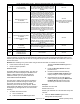
OV500G1
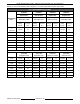
GAS SUPPLY LINE FLOW PRESSURE
NATURAL GAS PROPANE GAS
BTU/HR 180,000 180,000
W.C. 5.0" - 14.0" 12.0" - 14.0"
kCAL/HR 45,400 45,400
cm W.C. 12.7 - 25.4 30.5 - 35.6
Mj/HR 190 190
kPa 1.25 - 2.50 3.00 - 3.50
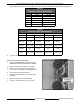
OV500G2
GAS SUPPLY LINE FLOW PRESSURE
NATURAL GAS PROPANE GAS
BTU/HR 300,000 350,000 300,000 350,000
W.C. 5.0 - 14.0" 6.0 - 14.0" 10.0" - 14.0" 12.0 - 14.0"
kCAL/HR 75,600 88,200 75,600 88,200
cm W.C. 12.7 - 35.6 15.3 - 35.6 30.5 - 35.6 30.5 - 35.6
Mj/HR 317 370 317 370
kPa 1.25 - 3.50 1.50 - 3.50 2.50 - 3.50 3.00 - 3.50
9. Turn gas valve off and disconnect manometer.
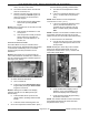
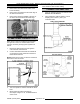
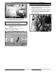
CROSS OVER TUBE ADJUSTMENT
1. Remove GAS MANIFOLD as outlined under
REMOVAL AND REPLACEMENT OF PARTS.
2. Remove burner rack enclosure - front panel.
3. Remove screw securing hot surface ignitor to
burner side rack assembly, and pull ignitor out.
4. Disconnect flame sensor lead wire.
5. Remove burner side rack and end shot burner
assembly.
6. Make sure burners are evenly spaced.
7. Check for .025" spacing in cross over tube.
F25361 (January 2010)
Page 37 of 60