
User manual


OV500 SERIES RACK OVEN - REMOVAL AND REPLACEMENT OF PARTS
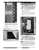
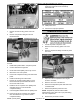
6. Access the thermostat bulb at top of the oven.
7. Remove screws securing probe cover from
oven.
8. Remove compression fitting and remove
thermostat bulb.
To install:
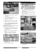
1. Install backup thermostat in component panel.
2. Connect lead wires to high limit.
3. Route thermostat capillary tube to top of oven.
4. Mark 8 3/4" from end of probe.
5. Insert male compression fitting onto thermostat
probe.
6. Install female fitting into bulb location.
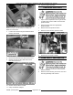
7. Insert 8 3/4" of backup thermostat into oven.
Ensure that backup thermostat bulb doesn't
touch inner walls of oven.
8. Install first set of 3 spacers over capillary tube
and allow them to go into the female
compression fitting.
9. Pack seal gasket material around capillary tube.
10. Insert second set of 3 spacers over capillary
tube and allow them to go into the female
compression fitting.
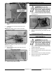
11. Tighten male compression fitting against
second set of spacers to secure backup
thermostat bulb.
12. Install probe cover.
13. Check oven for proper operation.
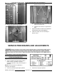
TEMPERATURE PROBE
1. Access the probe at top of the oven.
2. Remove screws securing probe cover from
oven.
3. Remove compression fitting and remove probe
from oven.
4. Open the control compartment door to gain
access to controller.
5. Remove cover from controller box.
6. Disconnect temperature probe lead wires from
controller board.
7. Remove temperature probe from oven.
NOTE: Temperature probe should be install
approximately 8 3/4" down from top of probe fitting
into oven compartment.
8. Reverse the procedure to install.
F25361 (January 2010) Page 26 of 60