
User Manual


Table Of Contents
4
Ⅴ.Structure of the products
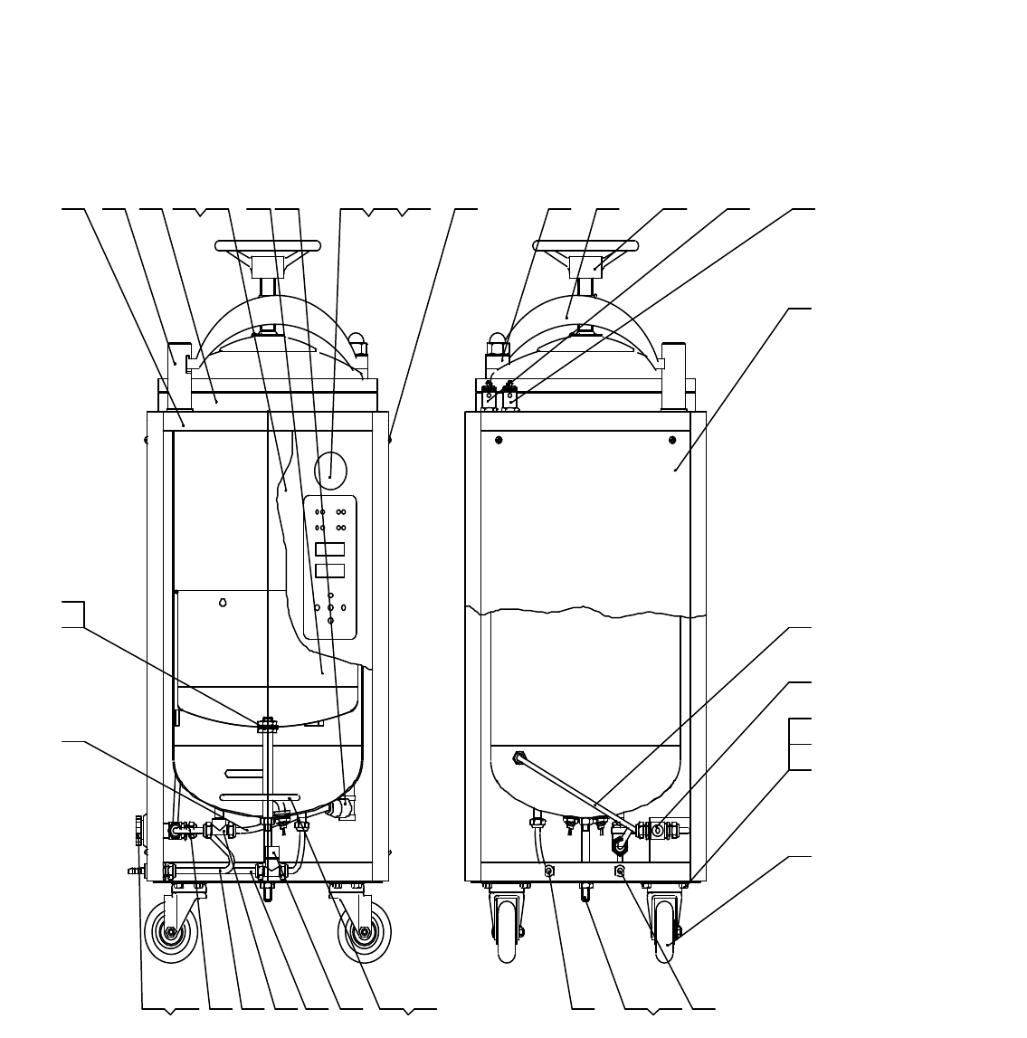
1. Locking by derrick wheel(XFH--)construction drawing
1 2 3 7 1 18 9 1 0654
1 7
1 8
2 2
2 1
2 0
2 3
1 9
1 61 51 2 1 41 3
2 6 2 5 2 42 9 2 83 03 6 3 5
3 8
3 9
3 7
34 33 3 2 3 1 2 7
1- Outer frame 2- fixed axis 3-the upper panel 4-the front panel 5-side/back panel 6-tank 7- water stage register
8- pressure gage 9-admission components 10-electrical controlling components 11---screws 12- shaft 13-crane 14-
derrick wheel 15- steam release valve 16- security valve 17-the left panel 18- cold air escape-pipe 19- four
way bale valve 20-bolts 21-nuts 22-spacer 23- wheeled walker 24-outer scupper 25-frame 26-nuts
27-outer admission pipe 28- heating tube 29-sealed tap 30(no) 31(no) 32- triple water valve 33- exhaust
steam pipe 34- pipe weep 35- exhaust steam turning handle 36-nuts 37- water level regulator adapter 38-internal
nuts 39-internal sealed taps