
User Guide


5G Starterkit User Guide
HMS Industrial Networks AB Page 6 of 12
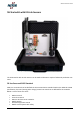
Antennas
Antennas are connected to the SMA connectors of the device.
Mount two stub antennas on the Wireless Router. These two antennas should be connected to the
ports marked Cellular 1 and Cellular 2.
For the 5G Wireless Router, 4 antennas are needed to achieve 3GPP compliance. In this case, the
additional two antennas should be connected to the ports marked GNSS and Cellular 3.
Connecting Ethernet
Two Ethernet cables are supplied with the Starterkit.
One Ethernet cable has an M12 connector. The M12 connector should be connected to the X22
port on the orange IO-Link master. The other end is connected to port 1 on the Wireless Router.
The other Ethernet cable is connected to Eth1 of the small gateway next to the IO-Link master (Eth1
is the top one). The other end of the cable is connected to port 2 of the Wireless Router.
Test the Sensors
At this stage it is possible to test the sensors.
When idle, the stack light should be displaying different “standby” patterns.
If an object is put in front of the laser distance sensor the stack light will switch mode and instead
show an indication of the distance.
When the push button is pressed, the stack light will show the signal strength of the Wireless
Router. If there is no connection to the Wireless Router, the stack light will show red.