
User's Manual


23
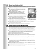
4. EQUIPMENT SETUP
4.1 Internal Message Repeater Setup
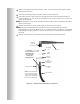
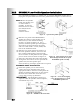
Locate and set the “Red Message” and “Green Message” slide switches and the “Red
Message Control” and “Green Message Control” DIP switches on the front panel of
the base station. Refer to section 6.9 for “Red Message Control” and “Green
Message Control” switch functions and message recording instructions.
If a System 30 Timer is installed with the Wireless IQ, the timer alert output can
be used to trigger tones in the headset or a message to be played by the message
repeater. Set “Red Message Control” and/or “Green Message Control” #5 switch to
ON for an alert message, which will be heard through outside speakers and/or
headsets selected with the #2, 3 and 4 switches only in headsets, or OFF for an alert
tone to be heard only in headsets.
If Wireless IQ message repeater will not be triggered by an alert signal, set both
“Red Message Control” and “Green Message Control” #5 switches to OFF so the
message repeater input will be triggered only by vehicle detector signals.
4.2 Early Warning Setup
An extra vehicle detector can be used with the Wireless IQ to give a pre-warning
signal when a vehicle enters the drive-thru area. To set up a pre-warning signal, first
install the extra vehicle detector at the desired detection point then connect its cable.
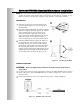
If an external vehicle detector is used, connect its cable to connector J9,
positions 1 and 2 on the base station audio circuit board.
If an internal Vehicle Detector Board is used, connect P1 on the VDB to J15 on
the Audio Circuit Board. Also on the Audio Circuit Board, wire the J25 connector,
positions 8 and 9 to the J9 connector, positions 1 and 2 respectively.
4.3 Dual-Lane Setup
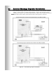
To set up the Wireless IQ system for dual-lane operation, place K1 DIP switch #1 on
the base station transceiver board in the ON position, then press the “Reset” button.
Refer to Figure 26 on page 35 and Figure 28 on page 37.
Set the “Green Message Control” DIP switch #8 to the ON position in the Secondary
Base only. The Primary Base must be wired to Lane 1, the Secondary Base to Lane 2.
4.4 Split-B Audio Setup
Split-B audio is used in dual-lane operations to limit audio transmission from Lane 1
COMMUNICATOR
®
s to be heard only by other Lane 1 Communicator operators, and
transmission from Lane 2 Communicators to be heard only by other Lane 2
Communicator operators. When the Split-B audio feature is not used, B audio
transmission from either lane is heard by all Communicator operators in both lanes.
To set up the Wireless IQ system for split-B audio operation, on the base station
transceiver board, place the K1 DIP switch #2 in the ON position, then press the
“Reset” button. Refer to Figure 26 on page 35 and Figure 28 on page 37.
4.5 Auto-Hands-Free Setup
Auto-Hands-Free operation is explained on pages 27 – 30. To set up the Wireless IQ
system for auto-hands-free operation, on the base station transceiver board, place
the K1 DIP switch #3 in the ON position, then press the “Reset” button.
Refer to Figure 26 on page 35 and Figure 28 on page 37.