
Installation Guide
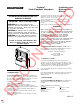

W H D Weight
13-1/8" 17-7/8" 7-7/8" 25 lbs.
Figure 1
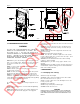
2.2 YOKE MOUNT INSTALLATION.
WARNING
DO NOT USE A PHOTOCONTROL IN A LOCATION
HAVING A UL CLASSIFICATION OF CLASS I, DIV. 2
OR CLASS II, DIV. 1. DO NOT USE FUSING IN A
LOCATION HAVING A UL CLASSIFICATION OF
CLASS I. FAILURE TO FOLLOW THESE WARNING
INSTRUCTIONS MAY RESULT IN FIRE AND
SIGNIFICANT PROPERTY DAMAGE.
2.2.1 Bolt the yoke to the mounting structure using either two 3/8"
bolts or one 1/2" grade 5 bolt. Tighten bolts securely (30-35 ft. lbs.
for 3/8" bolts or 50-60 ft. lbs. for 1/2" bolt). These bolts are not
provided.
2.2.2 Loosen the captive door screws attaching the door to the
housing. Open the door.
2.2.3 Detach the power disconnect plug from the disconnect
receptacle in the housing.
2.2.4 If needed, remove the door by removing the cotter pin from
the hinge pin and sliding the door hinge pins out of the housing.
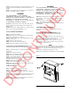
2.2.5 Use UL approved watertight fittings (not provided) on all
installations. If installed in a Marine location, use rigid metal conduit
or AVC Marine cable (not provided) and watertight cable grip fittings
(not provided) for power supply conductors.
NOTE
The threaded hole in the back of the housing is tapped for 1/2-14
NPT.
2.2.6 Remove clear protective cover and install watertight fitting.
Tighten securely.
2.2.7 Make all wiring connections in accordance with approved
wiring methods. Ensure that all supply wires and supply wire
connections are retained between the folds of the fiber heat shield
in the housing.
2.2.8 If the door was removed as in 2.2.3, reinstall the door by
sliding the door hinge pins into the housing. Insert the cotter pin
through the hinge pin.
2.2.9 Insert the door disconnect plug into the disconnect recep-
tacle in the housing.
2.2.10 Securely install the proper lamp type.
2.2.11 Close the door. Thread the captive door screws into the
housing. Tighten captive door sccrews to 55 in. lbs. torque. This is
required for watertight door seal.
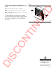
2.2.12 Refer to the identification label on the unit for mounting
restrictions. Aim the floodlight.
2.2.13 Tighten the yoke bolts securely (approx. 50 ft.lb. recom-
mended).
2.2.14 Energize the floodlight. Check its operation and for proper
area illumination. Adjust the aiming point as needed but within the
limits of the mounting restrictions.
3. MAINTENANCE
3.1 Relamping and cleaning.
3.1.1 Deenergize the floodlight.
3.1.2 Wipe off the exterior of floodlight to remove dirt or debris
that could enter when the door is opened.
3.1.3 Loosen the captive door screws attaching the door to the
housing. Open the door.
3.1.4 Remove the lamp type.
3.1.5 Securely install a proper new lamp type.
3.1.6 Wash both sides of the lens.
CAUTION
KEEP ELECTRICAL COMPNENTS DRY. DO NOT USE ABRASIVE
CLEANERS ON THE GLASS OR REFLECTOR LOSS OF OPTICAL
PERFORMANCE AND SUBSEQUENT GLASS BREAKAGE COULD
RESULT.
GR420
GR418
DISCONTINUED