
Instruction Manual

Copyright HK Instruments 2021 www.hkinstruments. Installaonversion7.02021
CAUTION!
•ForCEcompliance,aproperlygroundedshieldingcableis
required.
•Usecopperwireonly.Insulateorwirenutallunusedleads.
•Supplyaseparatecableforrelayandsignaloutwhenusingline
voltagetopowertherelay.
•Anywiringmaycarrythefulloperanglinevoltagecurrentbased
oneldinstallaon.Thecoverlockingscrewmustbeinstalledif
thelinevoltageissuppliedtotherelay.
•Careshouldbeusedtoavoidelectrostacdischargetothedevice.
•Thisunithasconguraonjumpers.Youmayneedtorecongure
thisdeviceforyourapplicaon.
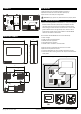
1)Routethecablesthroughthesquareopeninginthebackplateor
forsurfacewiringselectaknockoutonthetoporboomofthe
wallplate,asshowninFigure2a.
2)ConnectthewiresasshowninFigure2band2c.
STEP 3: CONFIGURATION
WIRING DIAGRAMS CONTINUED
Figure 2a - Roung the cables
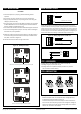
24 V
GND
A
B
Analog
+
Output 0/2–10 V / 4–20 mA
output
Figure 2b - Wiring diagram: Power input & signal output
Wires can be routed through the square opening in the back plate
Wires can be routed through the top knockouts
Wirescanberoutedthroughtheboomknockouts
NC
COM
NO
STEP 2: WIRING DIAGRAMS
Figure 2d - Wiring diagram: Relay
NOTE!Whenusinglongconneconwiresitmaybenecessarytousea
separateGNDwireforvoltageoutputcurrenttopreventmeasurementdis-
toron.TheneedforanextraGNDwiredependsonthecrossseconand
lengthoftheusedconneconwires.Iflongand/orsmallcrossseconwires
areused,supplycurrentandwireresistancemaygenerateavoltagedropin
thecommonGNDwireresulnginadistortedoutputmeasurement.
24 V
GND
A
B
+
Analog
Output 0/2...10 V
V
output
Figure 2c - Wiring diagram: Extra GND wire
ConguraonoftheRHT-MODseriesdeviceconsistsof:
1)Conguringthejumpers(seestep4)
2)Conguraonmenuopons.(Displayversionsonly.Seethe
usermanualforfurtherdetails)
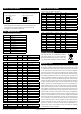
STEP 4: Jumper settings
(Grey colour indicates that a jumper is installed)
No jumper
Circuit open
Jumper installed
Circuit closed
Jumper stored
Figure 3 - Jumper installaon
1)Conguraonoftheoutputmodes:
Selecttheoutputmode,current(4–20mA)orvoltage(0–10V),
byinstallingjumpersasshowninFigure4.
Toselect2–10Voutputmodeonadisplayversionofthedevice:
First,select0–10Voutputbyjumper,thenchangethevoltage(V)
outputfrom0–10Vto2–10Vviatheconguraonmenu.Please
seetheusermanualformoredetails.