
Instruction Manual

Copyright HK Instruments 2022 www.hkinstruments. Installaonversion8.02022
SCHEMATICS
INSTALLATION
STEP 1: MOUNTING THE DEVICE
1)Mountthedeviceinthedesiredlocaon(seestep1).
2)Openthelidandroutethecablethroughthestrainreliefandconnectthe
wirestotheterminalblock(s)(seestep2).
3)Thedeviceisnowreadyforconguraon.
WARNING!Applypoweronlyaerthedeviceisproperlywired.
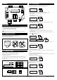
1)Selectthemounnglocaon(duct,wall,panel).
2)Usethedeviceasatemplateandmarkthescrewholes.
3)Mountwithappropriatescrews.
Display connecon
A
B
24 V
GND
LEDs
Joysck1
Joysck2
Joysck3
Select
Up
Down
Menu buons
Terminal
blocks
Pressure
sensor
Input terminal
configuraon
jumpers
Control out
Input
GND
GND
Figure 1a - Mounng orientaon
YES NO NO
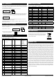
STEP 3: CONFIGURATION
2)Zeropointadjustment.Formoreinformaon,seeStep4.
PRESS. UNIT
Pa
SELECT
UP
DOWN
SELECT
ZERO SENSORS
SELECT
UP
DOWN
3)Selectthefunconingmodeofthecontroller:PRESSUREorFLOW.
-SelectPRESSUREwhencontrollingdierenalpressure.
Gotopoint3.1.
-SelectFLOWwhencontrollingairow.
Gotopoint3.2.0.
CONTROL UNIT
PRESSURE
SELECT
UP
DOWN
When control unit PRESSURE is selected.
3.1)Selectpressureunitfordisplayandoutput:Pa,kPa,mbar,inWCormmWC.
Thengotopoint4.
When control unit FLOW is selected.
3.2.0)Selectthefunconingmodeofthecontroller
-SelectManufacturerwhenconnecngDPT-Ctrl-MODtoafanwithpressure
measurementtaps.
-SelectCommon probewhenusingDPT-Ctrl-MODwithacommonmeasurement
probethatfollowstheformula:
q=k∙√∆P(i.e.FloXact)
MANUFACTURER
Common probe
SELECT
UP
DOWN
Common probe
Flakt Woods
SELECT
UP
DOWN
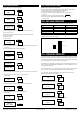
STEP 2: WIRING DIAGRAMS
ForCEcompliance,aproperlygroundedshieldingcableisrequired.
1)Unscrewthestrainreliefandroutethecable(s).
2)Connectthewiresasshowningure2aand2b.
3)Tightenthestrainrelief.
Figure 2a - Wiring diagram
A
B
24 V
GND
+ Power Supply
24VDC / 24VAC
Control out
Input
GND
GND
Modbus
Figure 2b - Wiring diagram example for input signals
Input
GND
ntc10k
J1
J2
J3
IN
Input ntc10k temperature:
Funcon04-Readinputregister3x0007
3.2.1)If
Commonprobe
selected:selectmeasurementunitsusedintheformula
(akaFormulaunit)(i.e.l/s)
b. If
Commonprobe
selectedinstep3.2.0:
EachcommonprobehasaspecicK-value.SelecttheK-valuefromcommonprobe
manufacturer’sspecicaons.
AvailableK-valuerange:0.001...9999.000
FORMULA UNIT
l/s
SELECT
UP
DOWN
3.2.2)SelectK-value
a.Ifmanufacturerselectedinstep3.2.0:
EachfanhasaspecicK-value.SelecttheK-valuefromfanmanufacturer’sspeci-
caons.
K-VALUE
9000.000
SELECT
UP
DOWN
3.2.3)Selectowunitfordisplayandoutput:
Flowvolume:m
3
/s, m
3
/h,cfm,l/s
Velocity:m/s,f/min
FLOW UNIT
m
3
/s
SELECT
UP
DOWN
1)Presstheselectbuonfortwosecondstoopenthedevicemenu.
4)SelecttheaddressforModbus:1...247
ADDRESS
99
SELECT
UP
DOWN
ItisrecommendedtouseshieldedtwistedpaircableforModbuscabling.
Thecableshieldmustbeearthedonlyinonepoint,normally,attheendof
themaincable.