
Instruction Manual

Copyright HK Instruments 2022 www.hkinstruments. Installaon version 7.0 2022
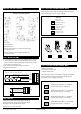
Figure 2a - Wiring diagram: Tout & Vout
Figure 2b - Wiring diagram: relay output
For CE compliance a properly grounded shielding cable is required.
1) Unscrew the strain relief and route the cable(s). Use the strain
relief on the le for power in and signal out (Tout/vout) and the
strain relief on the right for relay.
2) Connect the wires as shown in gure 2a and 2b.
3) Tighten the strain relief.
1) Select the desired measurement range (see step 3).
2) Select the desired measurement mode (see step 4).
3) Congure the relay (oponal) (see step 5).
The device is now ready to be used.
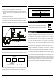
Congure the outputs:
• Temperature output (Tout)
• Velocity output (vout)
Select the output mode, current (mA) or voltage (V), by installing
jumpers as shown in Figure 4. Both outputs, temperature (T)
and velocity (v), are congured separately.
Tout
vout
24 V
GND
+
Power supply
24 VDC / 24 VAC
V A
V
A
Output 0...10 V / 4...20 mA (temperature)
Output 0...10 V / 4...20 mA (velocity)
No jumper
Circuit open
Jumper storedJumper installed
Cicuit closed
(Grey colour indicates that a jumper is installed)
Figure 3b - Jumper installaon
V
Temperature output (Tout): T = voltage (V)
Velocity output (vout): v = voltage (V)
T
v
mA
V
Temperature output (Tout): T = current (mA)
Velocity output (vout): v = current (mA)
T
v
mA
Temperature output (Tout): T = voltage (V)
Velocity output (vout): v = current (mA)
T
v
V mA
Temperature output (Tout): T = current (mA)
Velocity output (vout): v = voltage (V)
T
v
V mA
NC
COM
NO
STEP 2: WIRING DIAGRAMS
CONFIGURATION
STEP 4: SELECTING THE MEASUREMENT MODE
Figure 4
J1 Jumper (J1): Installed
J2 Jumper (J2): Not installed
Range 2 (0–2 m/s)
J1 Jumper (J1): Not installed
J2 Jumper (J2): Installed
Range 10 (0–10 m/s)
J1 Jumper (J1): Installed
J2 Jumper (J2): Installed
Range 20 (0–20 m/s)
Select the measurement range by installing jumpers as shown in
Figure 3a. (See Figure 3a-3b – Jumper sengs)
STEP 3: SELECTING THE MEASUREMENT RANGE
Figure 3a
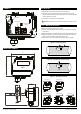
MOUNTING THE DEVICE COntinued
Figure 1d - Correct posioning of the probe:
minimum straight duct approach
Round ducts:
D = duct diameter
Rectangular ducts:
If there is a horizontal curve or change in the duct size,
D = width of the duct
If there is a vercal curve or change in the duct size,
D = height of the duct