
Instruction Manual

Copyright HK Instruments 2022 www.hkinstruments. Installaon version 7.0 2022
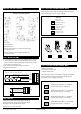
SCHEMATICS
DIMENSIONAL DRAWINGS
1) Mount the device in the desired locaon (see step 1).
2) Open the lid and route the cable through the strain relief and
connect the wires to the terminal block (see step 2). Use a separate
strain relief for each cable.
3) The device is now ready for conguraon.
WARNING! Apply power only aer the device is properly wired.
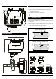
Figure 1a - Mounng a ange
Figure 1b - Mounng the probe in a ange
AVT
71.5
86
m/s
°C
36.0
95
210.0
15.0
15.0
70
Push buon
Terminal block
Jumpers
Terminal block
for relay
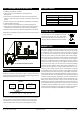
Air ow direcon
Air ow direcon
Air ow direcon Air ow direcon
Air ow direcon
Strain relief facing down
Figure 1c - Mounng orientaon
Tighten the
screw
INSTALLATION
1) Select the mounng locaon (on a duct).
2) Use the mounng ange of the device as a template and mark the
screw holes.
3) Mount the ange on the duct with screws (not included). (Figure 1a)
4) Adjust the probe to the desired depth. Ensure that the end of the
probe reaches the middle of the duct. (Figure 1b)
5) Tighten the screw on the ange to hold the probe in posion.
STEP 1: MOUNTING THE DEVICE