
User Manual

SW1
2-Position DIP Switch Toggle connection mode & CAN termination
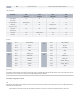
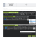
LED Indicators
Mode/State LED1
Bootloader
LED2
I2C Status
LED3
CAN Status
LED4
Power
Power Applied
No Firmware
Off Off Off On
Bootloader Mode Blinking quickly Off Off On
CAN Mode
DNA Server Found
Off Off Blinking at 1Hz On
CAN Mode
Awaiting DNA
Off Off Triple blink pattern On
I2C Mode Off Blinking at 1Hz Off On
No Power Off Off Off Off
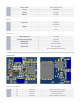
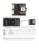
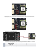
Pinouts
J1
Pin 1 VIN (5-36VDC)
Pin 2 CAN H
Pin 3 CAN L
Pin 4 GND
J4
Pin 1 STM32_VDD
Pin 2 UART3 TX
Pin 3 UART4 RX
Pin 4 SWDIO
Pin 5 SWCLK
Pin 6 GND
J2
Pin 1 VIN (5-36VDC)
Pin 2 I2C SCL
Pin 3 I2C SDA
Pin 4 GND
J5
Pin 1 +3V3
Pin 2 UART1 TX
Pin 3 UART1 RX
Pin 4 GPIO1 / ADC1_6
Pin 5 GPIO2 / ADC1_7
Pin 6 GND
Pitot Tube
The Airspeed Sensor should be connected to the pitot tube using 1/16” flexible tubing. Ensure that the tubing is secure on the barbs of the DLVR
pressure sensor. Tube order does not matter when configured appropriately in Ardupilot.
Ardupilot Integration Guide
I2C
Connecting to the Airspeed Sensor using the I2C connector uses a direct I2C connection for the DLVR pressure sensor. The MCU still boots but
is disconnected from the I2C bus.
Move position 2 of the DIP switch to the OFF position, towards the J2 connector. This places the Airspeed Sensor in I2C mode.