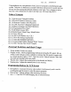
FCC ID: INSPECTS Congratulations on your purchase of the Lynx 3D computer controlled pistol grip system. Take time to familiarize yourself with these instructions for quick and easy set-ups and fine-tuning adjustments needed at your track. Now, prepare to take a step into a new dimension of control with the Lynx 3D from Hittite RCD! Table of Contents Pg. 1) Introduction/ External Switches Pg. 2) Physical Features/ Reference Guide Pg. 3) Electronic Features/ DCX Receiver. Pg.
Handle Switches 8. Dual Rate adjust: Selects the amount of travel the steering servo will turn. 9. ATL: Used to adjust the maximum amount of braking that will be applied when the brakes are fully engaged. (Nee: this is also the EPA (end point adjustment) for the brakes) Physical Features 10. Removable transmitter frequency module. 11. External charging jack: Port for charging cicadas with the supplied “overnight” charger. 12. Battery door: Access to the transmitter cicada battery box. 13.
Electronic Features The following features are described in depth throughout this manual. 3 Channel FM digital proportional system 10 model memory Model copy End Point Adjustment (EPA) Exponential (Steering and Throttle curve) Digital Dual Rate (Two modes) 1. Standard 2.
HF S-03MC Receiver: Included with the Lynx 3D (European version only) is the 03MC single conversion receiver. The 03MC is the best performing single conversion receiver available today and is also available separately in the U.S.A. as a lower cost alternative to the DCX. Note: When used with an ESC (Electronic Speed Control) the receiver is powered by the ESC through the throttle channel.
Transmitter Ni cads and Battery Charging; The Lynx 3D comes equipped with cicada batteries in the transmitter and an “overnight” charger for your convenience. To charge the batteries simply connect the charger to the charging port in the transmitter case or in the battery box. This can be done while the batteries are in or out of the transmitter. Normal charging time is approximately 12-18 hours. Caution: Batteries should not be left on charge for longer than 24 hours.
Now that you have familiarized yourself with the features and functions of the Lynx 3D, let’s discuss how to program them. Below is a reference of how the editing menu is laid out.
Edit Menu Access: To access the edit menu, turn the display or the power switch on, while pushing the “Edit” up/down keys simultaneously. Once you are in the edit menu use the up or down buttons to scroll through the options. To exit the edit menu push the “Edit” upend. keys simultaneously, the battery voltage will appear with the model number you are currently using, By using the down key the options will appear in the Hollowing order.
Model Reset: (Show picture of screen) This feature will allow you to reset any model back to the factory default setting. You must select the model to be reset in the model select “SL” screen. Once you have selected the proper model, push the “Data” incidence keys simultaneously, there will be an audible “beep” to verify reset. Model Copy: (Show picture of screen) This feature allows you to copy a per-existing program to another model number.
Timer: The timer can be selected to count up or down. Leave the setting at zero if you wish to count up. To count down, select the amount of time you wish from 1 — 60 minutes using the “Data” key incidence buttons. Once you have selected the time, it can be activated by pressing the “Edit” DN key after you are out of the programming menu. Racer Tip You can use the timer two ways, to count up or count down. If you want to see how long your car will run, use the count up setting.
ABS: (Anti-Lock Braking System) This feature is advantageous in applications where hard, late braking is required. First you must select the point you want the ABS system to override the standard braking. Mace the brake lever to the desired position and push the “Data” incidence keys simultaneously. Next use the “Aux.” keys to scroll through the ABS menu. Push the key to access the screen to turn the ABS feature on or off. Press the “Data” incidence keys simultaneously to turn it on and off.
Servo Reversing: This is used to change the rotating direction of your servos. Use the “Aux.” keys to select channel #1 (Steering), #2 (Throttle) or #3 (Aux). Normal rotation will look like “noR” and reverse will look like “Rev. To change these settings you will have to push the “Data” incidence key simultaneously. Exponential: This feature is used to change the control travel from linear to non-linear.
Auto Dual Rate: This feature allows you to select individual high and low speed steering travel. First you must set the throttle position where the rate will switch from #1 to #2. This is done by pulling the trigger to the desired position and pushing the “Data” incidence buttons simultaneously. A % will show up on the screen, this is the throttle % where the rate will change from this point, if you wish to change it repeat the procedure again.
This concludes the programming portion of the set up. Below are a few more tips on the Lynx 3D features that can improve your driving skills, Use of Trims: Steering: Make sure you have the steering trim at or very close to 0% when the horn and wheels are straight. If you change the neutral point too far from center you should re-position the servo horn to center. If the trims and horn are centered and the steering is still off, adjust the linkage to compensate.
D.S.C. (Direct Servo Control) This feature allows the operation of the receiver without transmitting a signal. Connect the DSC cord to the transmitter by plugging it into the jack on the left side of the transmitter face. (Note: The transmitter will turn on automatically but will not be transmitting a signal) Then connect the other end of the cord to the receiver in the Dschubba slot if using in conjunction with an ESC and to the external slot on the optional switch harness if used with a cicada battery.
Servo Selection: The Lynx 3D system does not come equipped with any servos so you will need to purchase a servo or two for your particular application. Here is a list of Hittites car and boat servos and their recommended applications.
1. FCC ID: SPECIFIC APPENDIX 6 TRANSMITTER TUNE-UP PROCEDURE Attach 9.6 Vdc power supply. Using a spectrum analyzer and a short pick-up antenna, look for 75 MHz signal with sufficient scan width to see 30-150 MHz spurious. Adjust T1, T2, T3 and T4, for maximum output at operating frequency and minimum output at any harmonics. Repeat Step 3. Check for minimum emissions from 30 to 760 MHz.
FCC ID: SPECIFIC APPENDIX 7 CIRCUITS AND DEVICES TO STABILIZE FREQUENCY Transmitter output frequency is determined and stabilized by PLL IC3 and 8 MHz reference crystal controlled oscillator.
FCC ID: SPECIFIC APPENDIX 8 CIRCUITS TO SUPPRESS SPURIOUS RADIATION, Final RF amplifier spurious emissions are attenuated by a "PI" matching network consisting of L2, €39, C41, T4, C42, TS, C43 and C11.