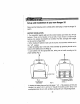
EE Set-up and installation of your new Ranger 2Z Please read the following section carefully before attempting to install the Ranger 2Z system. BATTERY INSTALLATION 1. The transmitter requires eight and the receiver battery pack needs four AA size batteries. These can be Alkaline or Ni-cad cells. If you choose to install Ni-cad batteries, the optional or Hittite overnight wall charger can be used to recharge them. 2.
a At this point, replace the alkaline cells or charge the batteries if they are Ni
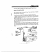
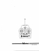
. Please refer to the instructions that accompany your electronic speed control for installation. OPERATION CHECK 1. Plug the switch harness and servo Connectors into the proper slots according to Fig. 1. The connectors are polarized, so they should fit into the receiver only in the proper way. NEVER USE EXCESSIVE FORCE TO PLUG IN CONNECTORS. 2. Ways turn the transmitter power switch “or first, before the receiver switch to avoid damaging your equipment. 3. Move the trim levers to the “neutral” position 4.
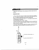
HELPFUL HINTS Antenna Both the transmitter and the receiver antenna must be fully extended when in use. Do not cut off any excess receiver antenna wire or bundle it up, this will cut down on the operating range of the system. Changing Frequency Hittite offers a matched pairs of TX and RX crystals to be used in changing the frequency of your Ranger 2Z system. Caution: frequency can be changed only within the same band, you cannot change from MHz to 40 or MHz just by changing crystals.
FCC ID: CLIFFHANGER APPENDIX 6 TRANSMITTER TUNE-UP PROCEDURE Attach 12.0 Vdc power supply. Using a spectrum analyzer and a short pick-up antenna, look for 75 MHz signal with sufficient scan width to see 30-150 MHz spurious. Adjust T1, T2, T3 and T4, for maximum output at operating frequency and minimum output at any harmonics. Repeat Step 3. Check for minimum emissions from 30 to 760 MHz.
FCC ID: IFHRANGER2ZA72Z APPENDIX 7 CIRCUITS AND DEVICES TO STABILIZE FREQUENCY Transmitter output frequency is determined and stabilized by crystal oscillator Qi.
FCC ID: CLIFFHANGER APPENDIX 8 CIRCUITS TO SUPPRESS SPURIOUS RADIATION, Final RF amplifier spurious emissions are attenuated by a "pI" matching network consisting of L2, C27, C30, T4, ¢33, and L5.