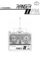
NON BEC 3 CHANNEL
WELCOME TO THE INTRIGUING WORLD OF R/C Thank you for purchasing the Ranger 3 channel FM radio system and thereby entering into the wonderful world of radio control model hobby. The Ranger 3 radio is the finest of its kind using the latest electronic technologies thereby assuring the best performance and highest quality. Team up with Hitec, “The R/cer’s Partner” and you will enjoy the many facets of R/C fun.
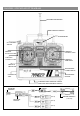
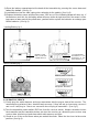
RANGER 3 CH FM LAYOUT DIAGRAM TRANSMITTER ANTENNA CARRYING HANDLE POWER METER CH 3 VARIABLE SWITCH STEERING CONTROL STICK NEUTRAL POSITION LEVER THROTTLE CONTROL STICK STEERING TRIM LEVER THROTTLE TRIM LEVER TRANSMITTER POWER SWITCH CONNECTOR JACK TRANSMITTER CRYSTAL STEERING SERVO REVERSE SWITCH THROTTLE SERVO REVERSE SWITCH RECEIVER ANTENNA RECEIVER SWITCH (CH 3) RECEIVER CRYSTAL (CH 2) (CH 1) BATTERY HARNESS (1.
THE VARIOUS USES OF THREE CHANNEL RADIOS A.VEHICLES & BOATS You can operate all model vehicles and boats of course with this advanced three-channel radio whether they are engine powered of battery operated. Since the basic maneuver of all vehicles and boats is throttle and steering (rudder), two-channel operation is all you need in most cases. However the third channel provides one more auxiliary channel you can use for whatever purpose you may desire. B.
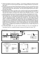
2) Open the battery compartment at the back of the transmitter by pressing the cover down and toward the bottom. (See fig 2) 3) Load batteries into the slots paying close attention to the polarity. (See fig 2) 4) Replace the battery cover and turn the power “ON” to see if the indicating arrow will move up.
4) Check the direction of the servo rotation. If you wish to change the direction of the servo, push the servo reversing switch and check if it changes direction as you desired. (See fig 4) 5) If you wish to have more forward throttle than backward, you can push down the neutral position adjustment lever. You will have 30% more forward than backward. The control stick will only return to the lower position. You may have to adjust the servo horn position when you do this.
INSTALLATION When installing the radio system to the model, please follow the detailed instructions for the model kit. A.Normal Installation (non BEC) If you are using the regular mechanical speed control that usually comes with the model kit, you will need both servos, and the battery harness that comes with the radio set. Incidentally this is the installation method for the engine equipped model as well. B.
D.WATER, DUST AND FUEL Take suitable measures to prevent water, dust and oil (fuel) from getting into the radio system. In the event that this does happen, make sure that you clean them off thoroughly before you turn it “ON” again. E.SERVO LINKAGE Install your linkage rod to product the maximum freedom of movement possible with the minimum amount of slop and friction; to check these points out, operate each servo over its full stroke and check if the rod binds or is loose.