Instruction Manual
LITE4 2.4 Instruction Manual Introduction Thank you for purchasing the LITE4 2.4 digital proportional radio control system. LITE4 2.4 is easy to use and utilizes the latest in solid-state components for unsurpassed reliability and performance. It is important that you read and understand this manual before you attempt to operate your system. *NOTE : LITE4 2.4 is Compatible With all Minima Series Receivers. (Not Compatible With Optima Series Receivers) Table of Contents Page 2. Page 3. Page 4. Page 5.
LITE4 2.4 Instruction Manual 1. TRANSMITTER A. Features - Ergonomically designed 4 channel 2.4GHz(AFHSS) transmitter. - High quality precision gimbals with adjustable stick length and tension. - Servo reversing on all channels. - V-tail and Elevon Mixing - Trainer system. (Slave mode only) - Dry battery pack for 4cells for Alkaline battery - Easy to read 1 LED battery indicators. - SIC (Simulator Interface Cable) Compatible B.
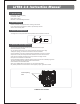
LITE4 2.4 Instruction Manual C. Specifications - Power supply : 6V 4cell Dry battery - Current drain : 100mA - Output power : 100mw - Modulation : 2.4G AFHSS Single Directional D. Servo Reversing - LITE4 2.4 transmitter is equipped with servo reversing on all channels. - If you need to change travel direction of rotation, open the battery case and move the servo reversing switch. E. Control Stick Adjustment - The length of the non-slip control sticks can be adjusted to suit the requirements of the user.
LITE4 2.4 Instruction Manual G. Trim Levers - The trim levers associated with each control stick are used to correct or (trim-out) the tracking of the aircraft. - (Caution) Make sure the trims will move the surface past neutral when moved to their extremes. This will assure you have adequate trim control. - After your plane's first test flight, note the positions of the control surfaces that required trim. Next, center the trims and turn the receiver off.
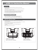
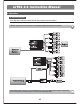
LITE4 2.4 Instruction Manual 3. Operation A. Connection Diagrams Glow, Gas, Nitro or Electric-Powered Aircraft Using a Separate Receiver Battery. Follow this connection diagram when using a dedicated 4.8 to 6.0V NiMH battery pack. Warning : Verify your servos are rated for use with higher voltage(7.4V) batteries or a regulator. 2.4GHz 6 Channel Aircraft Receiver 2.4GHz 6 Channel Aircraft Receiver Optional BEC shown in diagram.
LITE4 2.4 Instruction Manual B. Equipment Mounting Mounting When you mount each servo, use the supplied rubber grommets and insert an eyelet up through the bottom. Be sure not to over tighten the screws. If any portion of the servo case directly contacts the fuselage or the servo rails, the rubber grommets will not be able to attenuate vibration, which can lead to mechanical wear and possible servo failure.
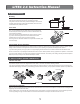
LITE4 2.4 Instruction Manual D. Antenna Installation (MINIMA 6S) The Minima 6S antenna system is made for high directivity consisting of two antennas. In order to maximize the functions of the Minimas, please install as shown below. TX 90˚ TX Recommended installation method to optimize receiver performance RX TX TX NOTE *Detailed range check mothod can be found on page 19.
LITE4 2.4 Instruction Manual 2. To use the trainer system between a STEREO Jack Transmitter and a DIN Jack Transmitter. (Needs trainer cable package #58321 between 6-cell battery radio and 8-cell battery radio systems). Please read the following instructions carefully for using transmitters with DIN Jack and/or stereo jack for the trainer system. You will need the Trainer cable full package (#58321).
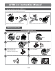
LITE4 2.4 Instruction Manual 4. Set-up and Use of the LITE4 2.4 To turn the system on and off, use the following sequence at all times. NOR NOR CH1 Link CH2 CH3 CH1 CH2 CH4 CH3 CH4 REV REV ELEVON OFF V-TAIL 2.4GHz 4 Channel Aircraft Radio NOR NOR CH1 Link CH2 CH3 CH1 CH2 CH4 CH3 CH4 REV REV ELEVON OFF V-TAIL 2.4GHz 4 Turning On -Turn on the transmitter, then turn on the receiver. Channel Aircraft Radio Turning Off -Turn off the receiver, then turn off the transmitter. A. ID-Setup A.K.
LITE4 2.4 Instruction Manual B. SmartScan Function Turn on the transmitter with pressing and holding the LINK button on the LITE4 2.4 for about 5sec. When RED LED is blinking rapidly, release the Link button. The LITE4 2.4 will automatically scan the frequency to find the cleanest and the most stable frequency in any area. When the scan is completed, the RED LED on the module stops blinking. Re-boot the transmitter (turn Off and On) and follow the link process with your receiver. LED & RED Push 2Sec.
LITE4 2.4 Instruction Manual D. Min. and Max. Range for Binding 5M(15ft) 50Cm(18in) NOR NOR Link CH1 CH2 CH3 CH1 CH2 CH4 CH3 CH4 REV REV ELEVON OFF V-TAIL 2.4GHz 4 Channel Airc raft Radio MIN RANGE MAX RANGE - Binding must be done within 15ft. (5m) of the transmitter and receiver. - The Transmitter and receiver need to be at least 18in. (45cm) from each other to bind properly. E. Receiver-Servo Connection List Receiver-Servo Connection List W/ LITE4 2.
LITE4 2.4 Instruction Manual F. Trim Adjustment This is a function for setting the trim values for each of the servos, allowing you to make adjustments to each individual servo independently of the trim switches located near the control stick of the radio (which can be adjusted in flight). We recommend that you first set up the model's servo pushrods so that the control surfaces are as centered as possible mechanically before attempting to adjust them in the trim switch.
LITE4 2.4 Instruction Manual H. S. REV (Servo Reverse) S. REV (Servo Reverse) When you first turn on your model, you will immediately see whether all the control surfaces are moving in the correct direction when you wiggle the controls. If any are moving in reverse, you can come to this screen to reverse the throw of the offending servo. Normal Reversed NOR REV Link ELEVON OFF V-TAIL CH1 CH2 CH3 CH4 2.
LITE4 2.4 Instruction Manual 5. Precautions - Always turn your transmitter on first and off last. - Never fly your airplane without first performing a proper range check. - FCC regulation in the USA prohibits consumers from changing the crystal in the transmitter. For channel changes send your system to an authorized service/repair center. - Never fly around or over houses, people or power lines. - Always charge your batteries before you fly. - Always fly responsibly and respect the rights of others.
openings and cause erratic operation or loss of control. If you must fly in wet weather during a contest, be sure to protect your transmitter with a plastic bag or waterproof barrier.
FCC Information to User This equipment has been tested and found to comply with the limits for a Class B digital device, pursuant to Part 15 of the FCC Rules. These limits are designed to provide reasonable protection against harmful interference in a residential installation. This equipment generates, uses and can radiate radio frequency energy and, if not installed and used in accordance with the instructions, may cause harmful interference to radio communications.
IMPORTANT Safety Instruction: 1) Read these instructions. 2) Keep these instructions. 3) Heed all warnings. 4) Follow all instructions. 5) Do not use this equipment near water. 6) Do not using near any heat sources such as radiators, heat resisters, stove, or other equipment that produce heat.
CONTACT INFORMATION Manufacturer Address : Lot 6 and 8, Blk. 24, Phase 4 CEPZ, Rosario, Cavite, Philippines To locate in-country Hitec RCD KOREA, INC. distributors of the LITE4 please refer to the Hitec RCD KOREA, INC. Website http://www.hitecrcd.co.kr/ These distributor(s) represent local contacts for this product. CORPORATE HEADQUARTERS: Hitec RCD KOREA, INC. 653, YangCheong-Ri, Ochang-Eup, CheongWon-Gun, Chung Buk Province, Korea Tel: 82-43-717-2071 Fax: 82-43-717-2193 Web: http://www.hitecrcd.co.
EUROPEAN UNION “DECLARATION OF CONFORMITY” DECLARATION OF CONFORMITY Hitec RCD KOREA, INC. 653, YangCheong-Ri, Ochang-Eup, CheongWon-Gun, Chung Buk Province, Korea declare under our sole responsibility that the product(s) 2.4GHz Radio Control System – LITE4 to which this declaration relate(s) is in conformance with the following standards: EN 301 489-1 V1.8.1:2008 EN 301 489-17 V2.1.1 :2009 EN60950-1:2006 EN 300 328 V1.7.1:2006 following the provisions of the 1999/5/EC Directives.
2.