X2 Ultima Multi-Chemistry, High-Output, Dual-Charger System Hitec RCD 2010 Version 1.
TABLE OF CONTENTS Introduction......................................................................................................................................02 Special features..............................................................................................................................04 Warning and safety notes..............................................................................................................
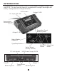
INTRODUCTION Congratulations on your choice of the X2 Ultima digital intelligent charger from Hitec RCD. You are now the owner of a professional charger/ discharger with battery management and integral balancer.
INTRODUCTION Please read this entire operating manual before using this product, as it covers a wide range of information on operation and safety. The unit is simple to use, but the operation of a sophisticated automatic charger/ discharger such as the X2 Ultima does require some knowledge on the part of the user. These operating instructions are designed to ensure that you quickly become familiar with its functions.
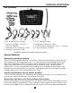
SPECIAL FEATURES Set contents 1 2 3 4 8 5 6 7 1. X2 Ultima Multi-Charger 5. RX Charging Cable 2. One XH Adaptor and One 6. Multiplex Charging Cable HP/PQ Adaptor 7. 18 AWG Wire Charging Cable – 2 pieces 3. Alligator Clip Charging Cable 8. Plug-in Battery Clamps 4. Tamiya Charging Cable Contents subject to change without notice Special features Opt imized operating software The X2 Ultima features the AUTO function that sets the feeding current during the charging or discharging process .
SPECIAL FEATURES Adaptable to various types of Lithium batteries The X2 Ultima is adaptable to various types of Lithium batteries, such as Li-Ion, LiPo and the new LiFe series of batteries. Fast and storage mode of Lithium batteries The purpose of charging Lithium batteries varies. The ‘fast’ charge mode reduces the duration of charging. The ‘store’ mode can control the final voltage of your battery, so as to store for a long time and protect the life of the battery.
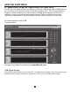
SPECIAL FEATURES PC- based analysis using USB Communication (for output 1 only) 7KH ; 8OWLPD LV ¿WWHG ZLWK D PLQL 86% SRUW RQ WKH IURQW VLGH RI WKH FDVH $ 86% ZLUH FDQ EH FRQQHFWHG WR WKLV VRFNHW LQ RUGHU WR OLQN WKH FKDUJHU WR D 3& 7KH &KDUJHU 0RQLWRU SURJUDP VFUHHQ HQDEOHV \RX WR YLHZ JUDSKV RI FKDUJH DQG GLVFKDUJH FXUYHV ZLWK D FDSDFLW\ YROWDJH WHPSHUDWXUH DQG DPSHUH GLVSOD\ (DFK LQGLYLGXDO FXUYH FDQ EH LQGLYLGXDOO\ VXSSUHVVHG RU VXSHULPSRVHG WR DOORZ D YLVXDO FRPSDULVRQ RI WKH GDWD 3& EDVHG
WARNING AND SAFETY NOTES These warning and safety notes are particularly important. Please follow the instructions for maximum safety; otherwise the charger and the battery can be damaged or at worst, cause a fire. Never leave the charger unattended when it is connected to its power supply. If any malfunction is found, TERMINATE THE PROCESS AT ONCE and refer to the operation manual. Keep the charger well away from dust, damp, rain, heat, direct sunshine and vibration. Never drop it.
WARNING AND SAFETY NOTES Never attempt to charge or discharge the following types of batteries: $ EDWWHU\ SDFN ZKLFK FRQVLVWV RI GLIIHUHQW W\SHV RI FHOOV LQFOXGLQJ GLIIHUHQW PDQXIDFWXUHUV $ EDWWHU\ WKDW LV DOUHDG\ IXOO\ FKDUJHG RU MXVW VOLJKWO\ GLVFKDUJHG 1RQ UHFKDUJHDEOH EDWWHULHV SRVH DQ H[SORVLRQ KD]DUG %DWWHULHV WKDW UHTXLUH D GLIIHUHQW FKDUJH WHFKQLTXH IURP 1L&G 1L0+ /L3R RU JHO FHOO 3E /HDG DFLG $ IDXOW\ RU GDPDJHG EDWWHU\ $ EDWWHU\ ILWWHG ZLWK DQ LQWHJUDO
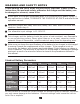
WARNING AND SAFETY NOTES batteries, in particular, should be charged according to the charging instructions provided by the manufacturer. Do not attempt to disassemble the battery pack arbitrarily. Please note that lithium battery packs can be wired in parallel and in series. In the parallel connection, the battery’s capacity is calculated by multiplying the single battery’s capacity by the number of cells when total voltage stays the same. The voltage’s imbalance may cause a fire or explosion.
PROGRAM FLOW CHART 10
LITHIUM POLYMER BALANCE CHARGE PROGRAM CONNECTION DIAGRAM &211(&7,1* 7+( &+$5*(5 7KH ; 8OWLPD FRPHV ZLWK PP PDOH EXOOHW FRQQHFWRUV DWWDFKHG WR WKH SRZHU ,1387 FDEOHV 7KHVH FDEOHV DWWDFK GLUHFWO\ WR PRVW KLJK TXDOLW\ $& '& SRZHU VXSSO\ XQLWV VXFK DV H)8(/ PRGHO 368 $ 9 $ $OVR LQFOXGHG DUH ODUJH WHUPLQDO FOLSV ZLWK PDWFKLQJ PP IHPDOH EXOOHW FRQQHFWRUV ZKLFK FDQ DWWDFK GLUHFWO\ WR 9 FDU EDWWHULHV ,W LV FULWLFDOO\ LPSRUWDQW WKDW \RX XVH HLWKHU D IXOO\ FKDUJHG FDU EDWWHU\ RU D KLJK TXD
LITHIUM POLYMER BALANCE CHARGE PROGRAM CONNECTION DIAGRAM Balance socket: The balance wire attached to the battery must be connected to the charger’s balancing port. Take care to maintain correct polarity! (See wiring diagram below) This diagram shows the correct way to connect your battery to the X2 Ultima while charging in the balance charge program mode only. WARNING: Failure to connect as shown in this diagram will damage this charger.
INITIAL PARAMETER SET UP (USER’S SET UP) Initial parameter set up (user’s set up): The X2 Ultima will be operated with the default value of the essential user settings when LW LV FRQQHFWHG WR D 9 EDWWHU\ IRU WKH ¿UVW WLPH 7KH VFUHHQ GLVSOD\V WKH IROORZLQJ information in sequence and the user can change the value of the parameter on each screen. When you are willing to alter the parameter value in the program, press the start/enter key to make it blink, then change the value with the Inc> or
INITIAL PARAMETER SET UP (USERS SET UP) DEC INC DEC INC DEC INC DEC INC DEC INC DEC INC DEC INC An optional feature uses the temperature probe contacting the surface of the battery. The temperature cut-off can be on or off. If it is on, set the maximum temperature at which the charger should allow the battery to reach during charge. Once a battery reaches this temperature during the charge, the process will be terminated to protect the battery.
LITHIUM BATTERY (LI-ION/LIPO/LIFE) PROGRAM Lithium battery (Li-Ion/LiPo/LiFe) program These programs are only suitable for charging and discharging Lithium batteries with a nominal voltage of 3.3V, 3.6V and 3.7V per cell. These batteries need to adopt a different charge technique termed constant current (CC) and a constant voltage (CV) method. The charge current varies according to the battery capacity and performance.
CHARGING LITHIUM BATTERY IN THE CHARGE MODE Charging Lithium battery in the charge mode This charging mode is for charging Li-Po/Li-Ion/LiFe batteries without a balance lead. The left side of the first line shows the type of battery you choose. The value on the left of the second line of the charger is the current user set up. After setting the current and voltage, press the Start/Enter key for more than 3 - + - + seconds to start the process (charge current: 0.1-10.0A, D EC INC DEC INC voltage: 3.7-22.
CHARGING LITHIUM BATTERY IN THE BALANCE MODE Charging Lithium battery in the balance mode This function is for balancing the voltage of Lithium-polymer battery cells while charging. In the balance mode, the battery needs to have a balance lead to connect to the individual balance port of the charger. You also need to connect the battery's power lead to the output of the charger.
CHARGING LITHIUM BATTERY IN THE FAST CHARGE MODE Charging Lithium battery in the fast charge mode The charging current gets smaller as the process nears the end term of the Lithium battery charging process. To finish the charging process earlier, this program eliminates certain terms of the CV process. Actually, the charging current will go to 1/5 from the initial value to end the process while the normal charging goes to 1/10 during the CV term.
CHARGING LITHIUM BATTERY IN THE STORAGE MODE Charging Lithium battery in the storage mode This is for charging or discharging a Lithium battery not to be used immediately. The program will determine whether to charge or discharge the battery to the certain voltage depending on the voltage of the battery at its initial stage. Different voltages exist for each type of battery: 3.75V for Li-Ion, 3.85V for LiPo and 3.3V for LiFe per cell.
CHARGING NICD/NIMH BATTERY IN THE CHARGE MODE Voltage balancing and monitoring in the discharge process The processor monitors the voltage of each cell in the battery packs during the “storage” and “discharging” process. If the voltage of any cell is abnormal, the X2 Ultima will show an error message and forcibly terminate the program. So if there is battery damage or a disconnection, you can see the error message and press the Inc button to know which cell is damaged.
DISCHARGE OF NICD/NIMH BATTERY Discharge of NiCd/NiMH battery - + DEC INC Batt type Stop Set the discharge current on the left and the final voltage on the right. The range of the discharge current is 0.1 ~5.0A; the range of the final voltage is 0.1~25.0V. Press the Start/Enter key for more than 3 seconds to start the program. - + DEC INC Start Enter '> 3 seconds' This screen indicates the discharging state. You can press the Start/Enter key to alter the discharge current.
CHARGING PB (LEAD-ACID) BATTERY IN THE CHARGE MODE Charging Pb (lead-acid) battery in the charge mode This program is only suitable for charging a Pb˄lead-acid˅battery with nominal voltage from 2 ~ 24V. The Pb˄lead-acid˅battery is completely different from the NiCd/NiMH batteries. These batteries deliver lower current in comparison to their capacity. The same restriction applies to the charging process. Consequently, the optimum charge current can only be 1/10 of the capacity.
STORAGE DATA PROGRAM Storage data program For your convenience, the X2 Ultima has a data storage and load program. It can store the data of ten batteries, representing the respective specifications of each battery. You can call back the data when charging or discharging without re-setting the program. Press the Start/Enter key to make it blink, and use the Inc or Dec to set up the parameter.
LOAD DATA PROGRAM Load data program This program loads the data stored at the “save data” program. Press the Start/Enter key to make the data field blink and press the INC or DEC for more than 3 seconds to load the data. Start Enter Choose the data number you want to call back. The data you want to call back will be displayed. Start Enter '> 3 seconds' Load the data.
WARNING AND ERROR MESSAGE The X2 Ultima incorporates various protective and monitoring functions to verify functionality and the state of its electronics. In the case of an error, the screen displays the cause of the error with an audible sound. Incorrect polarity connected. Battery connection interrupted. Short-circuit of the output termination. Wrong input voltage. Selection of the battery pack voltage is incorrect. Charger has malfunctioned for some reason. Seek professional advice.
RECOMMENDED ACCESSORIES Temperature Sensor Cable EH Adaptor XH Adaptor TP/FP Adaptor HP/PQ Adaptor Tamiya Charging Cable Alligator Clip Charging Cable JST/BEC Charging Cable Futaba RX Charging Cable 26
CONFORMITY DECLARATION The X2 Ultima satisfies all relevant and mandatory EC directives and FCC Part 15 Subpart B: 2008. For EC directives: The product has been tested to meet the following technical standards: This symbol means that you must dispose of electrical equipment seperately from general household waste when such equipment reaches the end of its useful life. Take your charger to your local waste collection point or recycling center.
MAXIMUM CIRCUIT POWER CHART Maximum circuit power chart (Output 1 & 2) The actual amount of charge current feeding to the battery is automatically limited to 200 watts each, so as not to exceed the charger's maximum rated charging power. The maximum discharge power is approximately 25 watts. The discharge current delivered to the charger is limited by the charger's internal thermal sensor for maximum discharge current.
MAXIMUM CIRCUIT POWER CHART Battery Type Specification Operating voltage range Circuit power DC 11.0~18.0 Volt Max. Charge power 2x200Watts Max. Discharge power 2x25Watts Charge current range Discharge current range Current drain for balancing Li-Po/Ion/Fe Li-Ion/Fe/Polymer cell count NiCd/NiMH battery cell count Pb battery voltage Net weight Dimension 0.1~10.0A 0.1~5.
COMMONLY USED TERMS Commonly used terms Final charge voltage: the voltage at which the battery's charge limit (capacity limit) is reached. The charge process switches from a high current to a low maintenance rate (trickle charge) at this point. From this point on, further high current charging would cause over-heating and eventual terminal damage to the pack. Final discharge voltage: the voltage at which the battery's discharge limit is reached.
Manufactured by Hitec RCD. www.hitecrcd.com All specifications and figures are subject to change without notice.