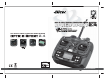
6CH 2.4GHz DIGITAL COMPUTER RADIO SYSTEM 2.4 6CH 2.4GHz DIGITAL COMPUTER RADIO SYSTEM 2.4 Bulit-in Hitec AFHSS 2.
Introducing the Optic 6 Sport Congratulations! You now own a basic, but unusually versatile and powerful, 6-Channel programmable RC transmitter. The Optic 6 Sport 2.4 is all the radio you need to fly most types of fixed-wings aircraft-from standard trainers to flying wings to 3-D aerobatic models to sailplanes (both powered or pure)-as well as most classes of helicopters.
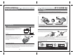
Vibration and Water Hitec AFHSS 2.4GHz Technology Vibration and Water The receiver contains precision electronic parts. Be sure to avoid vibration, shock, and temperature extremes. For protection, wrap the receiver in the provided "Flight Preserver" foam rubber, or use some other vibration-absorbing materials.
Connectors Operating with a Trainer Cord Be sure the alignment of a servo or battery connector is correct before inserting it into the receiver. To remove a connector from the receiver, try to pull on the connector's plastic housing rather than pulling on the wires. Pulling the wires can ruin the connector pins and break wires.
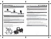
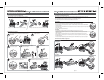
Flying Safety Stick Length Adjustment Hands come in all sizes so to accommodate everyone we use a two piece stick “top” that can be adjusted to fit a wide variety of users. Separate the top from the bottom piece and adjust the top piece to the length required. Screw the bottom up against the top piece to “jam” lock everything into position.
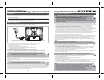
On-Off Switch Optic 6 Sport Controls and Switch Assignments Trim Switch SW 3 SW 1 Antenna This switch does more than just turn the radio on and off-it also gets you into the initial setup programs when you hold down the two "EDIT" buttons as you slide the switch from "off" to "on". SW 2 Trainer/Engine Cut Switch When you turn off the switch after making selections in the initial setup menu, you "lock" your choices into the radio for this particular model slot.
Joystick Controls Optic 6 Sport 2.4GHz Transmitter Features The following contains the complete instructions on how to use the Hitec AFHSS 2.4GHz system on Optic 6 Sport 2.4 and Optima series receiver set. We encourage you to review this information before using these products.
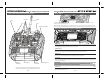
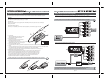
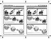
Optima 6 Receiver Features Optima Receiver Connection Diagrams As of this writing, there are three Optima 2.4GHz receivers that are compatible with the Hitec AFHSS 2.4GHz System. The Optima 6, Optima 7 and the Optima 9 are loaded with a variety of functions that are sure to deliver a satisfying R/C experience. Glow, gas, nitro or electric powered aircraft using a separate receiver battery. Follow this connection diagram when using a dedicated 4.8 to 6.0V NiMH battery pack, or *2S Li-Po/Fe 7.4V batteries.
Optima Series Receiver Features Optima Series Receiver Features and setup Set-up and Use of the Hitec 2.4GHz System Scan Mode and Normal Mode Selection To turn the system on and off, use the following sequence at all times Hitec’s Spectra 2.4GHz module and Optima series receivers have two different operational modes to choose from, “Normal Mode” or “Scan Mode.” There are available 2.4GHz channels that can be used by your Hitec AFHSS 2.4 system.
Set-up and Use of the Hitec 2.4GHz System Optima Series Receiver Features and setup Switching from Normal Mode to Scan Mode Switching from Scan Mode to Normal Mode You will hear four short beep sound for Normal Mode Turn on transmitter, then the receiver. 3Sec. Turn on transmitter, then the receiver. You will hear two short beep sound for Scan Mode 3Sec. 3Sec. After connected, make sure you have control over the model.
Set-up and Use of the Hitec 2.4GHz System Always do a pre-flight function check Optima Series Receiver Features and setup FAIL-SAFE Setup Before the engine or motor is started, turn on the system as explained above. Then make sure all the servos and control surfaces are working properly. If any control surface is not moving properly, do not fly the aircraft until the problem is solved.
Optima Series Receiver Features and setup Optima Series Receiver Features Testing the FAIL-SAFE Setting Telemetry System a. Move the sticks to positions other than the FAIL-SAFE settings, and then switch off the transmitter. The servos should now move to the FAIL-SAFE positions previously stored, after the HOLD period (1 sec.) has elapsed. Currently there is a direct feedback telemetry function available in your Hitec 2.4 system. Plans are to have many more devices available in the future.
Transmitter Displays and Messages Receiver-Servo Connection List FAIL-SAFE and Hold Mode Warning Display (Low voltage) The table below shows where the aircraft's servos should plug into a six-channel receiver. Note that some functions shown will not operate until they are activated in the transmitter. The standard function is listed first for each channel. When the battery's voltage drops to 6.6 volts, this number starts blinking on the screen and the transmitter begins to steadily beep.
Initial Setup Menu Programming for All Aircraft Before you turn on the transmitter to begin programming one of the model slots for your aircraft, refer to the servo connection chart on page 12, to see how to plug the servos into their proper channel sockets in the receiver. Don't turn on the receiver in your model just yet - we'll tell you when to do so.
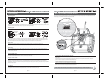
Optic 6 Sport ACRO in-Flight Controls SW 3 Model Setup Menu Programming for Powered Airplanes (ACRO) ACRO Functions Map EPA End Point Adjust (Servo travel) EXP Exponential Settings S-REV SERVO Reverse ELVN Elevon Mixing (Tailless models) V-TAL V-tail Mixing E->F Elevator Flap Mixing CAMB Camber (Combined Flaps & Ailerons) Antenna Trim Switch SW 2 SW 1 27 28 29 29 30 32 34 D/R S-TRM P.MIX FLPN A->R CUT FLT.
EPA (End Point Adjustment) EPA (End Point Adjustment) EPA (End Point Adjustment) Elevator End Points The EPA function is used to set (or limit) the travel of each servo, and may be set anywhere from 0% and 125% for each travel direction. Reducing the percentage settings reduces the total servo throw in that direction. The EPA function is normally used to prevent any servos from binding at the ends of their travel.
D/R (Dual Rate) EXP (Exponential Rate) EPA (End Point Adjustment) EXP (Exponential) If this is your first computer radio, you may have never been introduced to dual rates before.
S. TRM (Sub Trim) P. MIX (Programmable Mix) S. TRM (Sub Trim) P. MIX (Programmable Mix) This is a programmable function for setting the subtrim values for each of the servos, allowing you to make fine adjustments to each individual servo independently of the trim buttons located on the radio case (which can be adjusted in flight).
ELVN (Elevon Mix) FLPN (Flaperon) ELVN (Elevon mix) Setting up flaperons CH1 CH2 Aileron Operation 1) Activate the program by pushing both DATA buttons-the "Inh" symbol changes to the default 100% value. With your model turned on, test the ailerons by moving the joystick to the right and to the left: To the right, the right-hand aileron should go up while the left-hand aileron goes down. If this isn't happening, go to the S REV screen and reverse the offending aileron.
A → R (Aileron-Rudder Mix) CUT (Engine Cut Function) A R (Aileron-Rudder Mix) CUT (Engine Cut Function) In this screen you can set the throttle's servo travel value (you can also choose the direction in the program) so that you can immediately cut off the motor when the engine is below half throttle with a push of the "Eng Cut" button located on the upper right-hand corner of the transmitter case.
FLT. C (Flight Conditions) FLT. C (Flight Conditions) Setting Up Flight Condition Modes with Different Dual Rate and Exponential Values FLT. C (Flight Conditions) Let's set up two dual-rate and exponential settings in addition to those established with the switch SW-3 in the center, normal (NOR) position.
Optic 6 Sport Sailplane in-Flight Controls Sailplane Controls and Switch Assignments To avoid duplication of text within the manual we suggest that if you have not already read the following you refer to this previously shown information in the front of the manual. Antenna Trim Switch SW 3 SW 2 SW 1 Trainer/Engine Cut Switch GLID FUNCTIONS MAP EPA D/R EXP S.TRM S.REV P.MIX STCK V.TAL A->R E->F CROW CAMB ADIF FLT.
Initial Menu Feature Review for GLID Programming ADIF (Aileron Differential) The following item is located in the Initial Menu as described on page 13 -15. We will review it here. ADIF (Aileron Differential) Select the Model type baseline: In the second menu screen, the programming baseline of ACRO, GLID, or HELI will be blinking. Since we are setting up a Sailplane, select GLID by scrolling to it with a CURSOR button.
CROW (Glide-Path and Airspeed Control) CAMB (Wing Camber) CROW (Glide-Path and Airspeed Control) Launch: When switch SW-3 is pulled toward you the ailerons and flaps will rise together slightly to "reflex" the airfoil for high-speed flight and the elevator will kick up a few degrees to rotate the model vertical in the first 5 seconds or so of flight.
Optic 6 Sport Heli In-Flight Controls Optic 6 Sport Manual for Helicopters This section covers the Optic 6 Sport programming that is specific to the HELI mode for flying a model Helicopter. If this is your first Heli To avoid duplication of text within the manual we suggest that if you have not already read the following you refer to this previously shown information in the front of the manual.
Model Setup Menu Programming Model Setup Menu Programming for Helicopter To set up the Optic 6 Sport 2.4 to fly a particular model, you need to get into the radio's model setup menu. In this menu you can program specific control functions and the value (the amount of servo travel) for the particular model helicopter you selected earlier in the initial setup menu. This section describes how to use the Optic 6 Sport 2.4’s helicopter functions (model type HELI).
T.CV (Throttle Curve) The throttle & pitch curves are tied to the position of the Throttle / Collective stick, and are specified at five points labeled 1through 5 below. These "curves" are really straight lines connecting the settings at the five points, and are defined by assigning servo movement percentages to five positions of the left stick: Lowest stick position = Point 1, 1/4-up stick position = Point 2, Half-stick = Point 3, 3/4 position = Point 4, Top stick position = Point 5.
HOLD (Throttle Hold) GYRO (Gyro Gain) GYRO (Gyro Gain) HOLD (Throttle Hold) Gyro settings are used to automatically control the gyro's gain in all 4 different flight modes. It may be set to different values in NOR, ST1, ST2, and ST3 flight modes, allowing you to pick the gain you need for each circumstance. The Gyro settings control the output at receiver CH5. You cannot independently control this channel with a switch. There are many manufacturers of gyros. Not all of their setup are the same.
SWAH (120 Swash Plate Programming) OPTIC 6 SPORT ACRO DATA SHEET 4. Call up the swash screen by repeatedly pressing one of the Up Down EDIT buttons until the SWAH window appears. The function is automatically active when you select 120 mixing in the model setup menu. 5. If all the servos raise the swash with increasing collective, go to the next step. If they lower the swash, press the CURSOR Right button twice to get to the collective setting menu (the arrow appears over the number 6).
OPTIC 6 SPORT GLID DATA SHEET MODEL TYPE : GLID MODEL NAME : 0 1 2 MODEL TYPE : HELI 3 4 CH1 EPA OPTIC 6 SPORT HELI DATA SHEET SFT : N , P 5 6 7 CH2 8 9 CH3 . MODEL NAME : 0 CH4 CH5 % L/U % L/U % L/U % L/U % L/U % R/D % R/D % R/D % R/D % R/D % R/D % % % % 1 % % % % % % 1 % % % % % S.TRM S.