
User Manual

Page 9
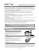
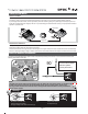
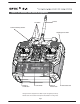
Optic 5 2.4 Controls and Switch Assignments
This figure shows the assignments for a Mode 2 system as supplied by the factory.
Note that some of the functions will not operate until activated in the mixing menus.
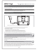
Gear/Engine Cut Switch
Rudder &
Throttle Stick
Aileron &
Elevator Stick
Plastic Side Panel
Antenna
Trim Switch
Power/Low Battery Indicator
Power Switch
5
5