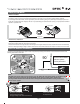
- Telemetry Capabilities (w/optional Optima Receivers) - 1024 Resolution - High Precision Quad Ball Bearing Gimbals - Digital Trim with Beep Sound - All Channel Servo Reversing - 5th Channel AUX Switch for Retracts or Engine Cut - Elevon Mixing (Ch.1 & 2) - V-Tail Mixing (Ch.2 & 4) - ATV on Ch.
5 5 Table of Contents Set-up and Use of the Hitec 2.4GHz System Receiver-Servo Connection List ATV (Adjustable Travel Volume) Function Trim Adjustment S. REV (Servo Reverse) ELVN (Elevon Mix) V.
5 5 Introducing the Optic 5 2.4 Congratulations and welcome to the R/C world! You now own a basic, but unusually versatile and powerful, 5-Channel beginner’s RC transmitter. The Optic 5 2.4GHz is all the radio you need to fly most 5-Channel fixed-wing aircraft. Standard features include servo-reversing for all channels and trim adjustments on all control channels, ATV (Adjustable Travel Volume) on Aileron (CH.1) and Elevator (CH.2). The Optic 5 2.
5 5 Hitec’s AFHSS 2.4GHz Technology Hitec is proud to introduce our first 2.4GHz built-in 2.4 transmitter. The Optic 5 2.4 can be used with most of the Hitec’s existing AFHSS (Adaptive Frequency Hopping Spread Spectrum) 2.4GHz receivers. Other features of our system include telemetry capabilities, our exclusive BODA(Boosted Omni-Directional Antenna) system and a SPC(Supplemental Power Connection) for added insurance.
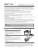
5 Vibration and Water Vibration and Water The receiver contains precision electronic parts. Be sure to avoid vibration, shock, and temperature extremes. For protection, wrap the receiver in the provided "Flight Preserver" foam rubber, or use some other vibration-absorbing materials. If you are flying near bodies of water, it's also a good idea to protect the receiver by placing it in a plastic bag and securing the open end of the bag with a rubber band before wrapping it with foam.
5 5 Connectors Be sure the alignment of a servo or battery connector is correct before inserting it into the receiver. To remove a connector from the receiver, try to pull on the connector's plastic housing rather than pulling on the wires. Pulling the wires can ruin the connector pins and break wires.
5 5 Operating with a Trainer Cord When used as a student radio, the Optic 5 supports the trainer system. Instructions below provide general information about the trainer system and which method may work for you. NOTE: 1. WHEN USING THE TRAINER SYSTEM IN THE STEREO JACK TO STEREO JACK FORMAT AS NOTED IN THE NEXT SEVERAL PARAGRAPHS, BOTH TRANSMITTERS ARE GOING TO TRANSMIT. 2. IF THE STUDENT TRANSMITTER HAS A REMOVABLE MODULE, REMOVE IT. THEN, IT WILL NOT BE TRANSMITTING.
5 5 Stick Length Adjustment Everyone's hand size is different, so in order to accommodate all, we use a two piece stick “top” that can be adjusted to fit a wide variety of users. Separate the top from the bottom piece and adjust the top piece to the length required. Screw the bottom up against the top piece to “jam” lock everything into position.
5 5 Flying Safety To ensure your own safety and the safety of others, please observe the following precautions: Flying field We recommend that you fly at a recognized model airplane flying field. You can find model clubs and fields by asking the nearest hobby dealer, or contacting the Academy of Model Aeronautics. Always pay particular attention to the flying field's rules, as well as the presence and location of spectators, the wind direction, and any obstacles on the field.
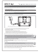
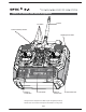
5 5 Optic 5 2.4 Controls and Switch Assignments Trim Switch Antenna Power/Low Battery Indicator Gear/Engine Cut Switch Rudder & Throttle Stick Power Switch Aileron & Elevator Stick This figure shows the assignments for a Mode 2 system as supplied by the factory. Note that some of the functions will not operate until activated in the mixing menus.
5 5 On-Off Switch This switch does more than just turn the radio on and off, it also allows you to link to the receivers (see page 13). Optic 5 2.4 Programming Switches and Buttons "ATV" potentiometer The ATV function is somewhat similar to EPA (End Point Adjustment) and D/R (Dual Rate) function; it allows you to adjust a servo’s travel end positio amount over a control stick‘s movement.
5 5 Hitec AFHSS 2.4 GHz Receiver system As of this writing, there are three Optima and two Minima 2.4GHz receivers that are compatible with Hitec AFHSS 2.4GHz System. The Optima 6, Optima 7, Optima 9 and the Minima 6T and 6E are loaded with a variety of functions that are sure to deliver a satisfying R/C experience. The Minima 6T(or Minima 6E) receiver is offered as a standard receiver for the Optic 5 and you can purchase an Optima series receiver to utilize the “telemetry function”.
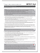
5 5 Minima 6T Receiver Connection Diagrams Glow, Gas, Nitro or Electric-Powered Aircraft Using a Separate Receiver Battery. Follow this connection diagram when using a dedicated 4.8 to 6.0V NiMH battery pack. Warning : Verify your servos are rated for use with higher voltage(7.4V) batteries or a regulator. 2.4GHz 6 Channel Aircraft Receiver Electric-Powered Aircraft with Electronic Speed Control Use this method on electric planes using ESCs providing power, A.K.A.
5 5 Minima Series Receiver Features Set-up and Use of the Hitec 2.4GHz System To turn the system on and off, use the following sequence at all times. Turning On -Turn on the transmitter, then turn on the receiver. Turning Off -Turn off the receiver, then turn off the transmitter. ID-Setup A.K.A, Link or Bind Press and hold the button on the front of the transmitter, and turn on the transmitter. Release the link button. Press and hold the LINK button on the Receiver and turn on the power.
5 5 Minima Series Receiver Features 8 8 [Minima or Micro series Receivers] When they are turned on again, the RED LED on the module(or radio) and the BLUE LED on the receiver will glow steady. [Optima series Receivers] When they are turned on again, you will hear a continuous beep sound. Both RED LEDs on the module and receiver will glow steady in normal status. el nner haeiv C 6 ec z R H ft G a .4 r 2 irc A SmartScan Function The SmartScan is a unique function of Hitec’s AFHSS 2.
5 5 Minima Series Receiver Features and Set-up FAIL-SAFE and Hold Mode Set-up Switch on both. Wait for the system to boot and gain control over the model. Press and hold the button on the Minima until the LED turns off l ner n e ha iv C ce e 6 z R H ft G a .4 cr 2 ir A el nner ha iv C e 6 ec z R H t G raf .4 2 irc A el nner ha iv C e 6 ec z R H ft G a .4 r 2 irc A 6Sec. el nner ha iv C e 6 ec z R H t G raf .4 2 irc A l ner n e ha iv C ce e 6 z R H ft a G .
5 5 Minima Series Receiver Features Testing the FAIL-SAFE Setting a. Move the sticks to positions other than the FAIL-SAFE settings, and then switch off the transmitter. The servos should now move to the FAIL-SAFE positions previously stored, after the HOLD period (1 sec.) has elapsed. How to turn FAIL-SAFE Off and reactivate the Hold Mode a. Switch on the transmitter, then the receiver. Wait for the system to boot and you have control over the model. b.
5 5 Set-up and Use of the Hitec 2.4GHz System 5M(15ft) 50Cm(18in) MIN RANGE MAX RANGE - Binding must be done within 15ft. (5m) of the transmitter and receiver. - The Transmitter and receiver need to be at least 18in. (45cm) from each other to bind properly. - In the ScanMode, if the transmitter or receiver has been shut off or disconnected for more than one second, both the module and receiver need to be re-booted (turn the power off and back on).
5 5 ATV (Adjustable Travel Volume) Function The ATV function is somewhat similar to the EPA (End Point Adjustment) and D/R (Dual Rate) functions; it allows you to adjust a servo’s travel end position amount over a control stick‘s movement. The ATV function affects both endpoints at once, while the EPA function allows each servo to travel individually. This function can be found useful when the plane is too sensitive over a control stick’s movement.
5 5 S. REV (Servo Reverse) S. REV (Servo Reverse) When you first turn on your model, you will immediately see whether all the control surfaces are moving in the correct direction when you wiggle the controls. If any are moving in reverse, you can come to this screen to reverse the throw of the offending servo.
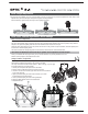
5 5 V.TAIL (V-Tail) V.TAIL (V-Tail) This is another built-in mixing program available on the Optic5 that mixes the rudder and elevator servos for controlling V-tailed aircraft. Similar to elevon programming, the two surfaces can move up and down together (for elevator control) or opposite (for rudder control in this case). CH2 CH4 Up Elevator CH2 CH4 Right Rudder (view from rear) Surfaces can move up and down together (for elevator control) or opposite (for rudder control in this case).
5 5 Service & Support Hitec Customer Service Help is available from Hitec customer service through phone support and e-mail inquiries. Our US office is generally open Monday thru Friday, 8:00AM to 4:30PM PST. These hours and days may vary by season. Every attempt is made to answer all incoming service calls. Should you get our voice mail, leave your name and number and a staff member will return your call. Hitec Website Make plans to visit the Hitec website, www.hitecrcd.com, on a regular basis.
5 5 MEMO Page 22
The Optic 5 is Hitec's most affordable, simple stick radio equipped with our built-in AFHSS 2.4GHz technology, pre-programmed mixes and simple plug-and-fly link system. All these features make the Optic 5 the perfect match for any beginner's needs.