
User's Manual


Using Intelligent Input Terminals
Operations
and Monitoring
4–30
PID ON/OFF
and PID Clear
The PID loop function is useful for controlling motor speed to achieve constant flow, pressure,
temperature, etc. in many process applications. The PID Disable function temporarily suspends
PID loop execution via an intelligent input terminal. It overrides the parameter A071 (PID
Enable) to stop PID execution and return to normal motor frequency output characteristics. the
use of PID Disable on an intelligent input terminal is optional. Of course, any use of the PID
loop control requires setting PID Enable function A071=01.
The PID Clear function forces the PID loop integrator sum = 0. So, when you turn ON an intel-
ligent input configured as [PIDC], the integrator sum is reset to zero. This is useful when
switching from manual control to PID loop control and the motor is stopped.
CAUTION: Be careful not to turn PID Clear ON and reset the integrator sum when the inverter
is in Run Mode (output to motor is ON). Otherwise, this could cause the motor to decelerate
rapidly, resulting in a trip.
Opt.
Code
Symbol Function Name
Input
State
Description
23 PID PID Disable ON Disables PID loop execution
OFF Allows PID loop execution if A71=01
24 PIDC PID Clear ON Force the value of the integrator to zero
OFF No change to PID loop execution
Val id for
inputs:
C001, C002, C003, C004,
C005, C006, C007, C008
Required
settings:
A071
Notes:
• The use of [PID] and [PIDC] terminals are
optional. Use A071=01 if you want PID loop
control enabled all the time.
• Do not enable/disable PID control while the
motor is running (inverter is in Run Mode).
• Do not turn ON the [PIDC] input while the
motor is running (inverter is in Run Mode).
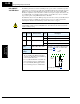
5 3 1
7 6 4 2
8
FW
TH
PLC
CM1
P24
CM1
See I/O specs on page 4–9.
Example: (Requires input configuration—
see page 3–47
. Jumper position shown is
for –xFU/-xFR models; for –xFE models,
see page 4–12
.)
PIDC
PID