
User Manual


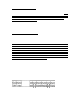


Example 2
Logic 1
To Valve
12 Ga
Table
Voltage drop
from Chart
Controller to
V1
500´@ 3
valves
1.215 V.D.
V1 to V2 700´@ 2
valves
1.134 V.D.
Total Voltage drop 3.159 O.K. use 12 Ga
24 Volts less 3.159 = 20.841 Volts
V2 to V3 1000´@ 1
valve
0.810 V.D.
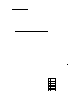
Logic to V1 V1 to V2 V2 to V3
500´ 700´ 1000´
Chart 2
.35 amps inrush charts Voltage Loss .25 amps holding chart Voltage Loss
Length
1 Valve 2 Valves
3 Valves
4 Valves
Length 1 Valve
2 Valves
3 Valves
4 Valves
Wire Size 12 1.62 R factor Wire Size 12 1.62 R factor
100 0.113 0.227 0.340 0.454 100 0.081 0.162 0.243 0.324
200 0.227 0.454 0.680 0.907 200 0.162 0.324 0.486 0.648
300 0.340 0.680 1.021 1.361 300 0.243 0.486 0.729 0.972
400 0.454 0.907 1.361 1.814 400 0.324 0.648 0.972 1.296
500 0.567 1.134 1.701 2.268 500 0.405 0.810 1.215 1.620
600 0.680 1.361 2.041 2.722 600 0.486 0.972 1.458 1.944
700 0.794 1.588 2.381 3.175 700 0.567 1.134 1.701 2.268
800 0.907 1.814 2.722 3.629 800 0.648 1.296 1.944 2.592
900 1.021 2.041 3.062 4.082 900 0.729 1.458 2.187 2.916
1000 1.134 2.268 3.402 4.536 1000 0.810 1.620 2.430 3.240
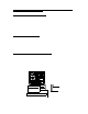
WIRE CONNECTIONS:
One of the most critical installation requirements of a Logic 2 wire system is the quality
of your wire connections. If you follow these directions you will have a reliable,
dependable control system for many years. It is suggested to soldier all receiver (red
wire) connections to your main two-wire run. Next install the soldiered two-wire
connection in a waterproof underground connector housing. When soldering is
impractical, a waterproof “dry-type” connection such as the Hit Products DBC-Y or
DBC-R or 3M DBY™ or DBR™ wire connector is required. Either of the above
mentioned products will provide an uncontaminated, dry connection and then the splice is
submerged in a waterproof gel- filled housing.
4