Logic 2 and Logic 3 Two Wire Irrigation Controllers P.O. Box 929, 556 S. Mirage Avenue Lindsay, CA 93247 For Technical Assistance: 800-468-0071 ext.
TABLE OF CONTENTS 1. Installing the Logic 2 and Logic 3, Valve Wiring 2. Valve Wiring 3. Selecting Proper Wire Size 4. Wire Connections 5. Testing Controller Surge Protection Board 6. Controller Lightning Protection 7. Features and Programming the Logic 2 and the Logic 3 8. Pre Wet, Fertigation and Setting Pause 9. Start Times, Total Run Times and Calendar 10. Definitions and Looping Program 6 11. Program/Master Valve ON/OFF, Test Cycle 12. Semi/Manual/Program Clear, Rain Delay, Run 13.
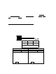
INSTALLING THE LOGIC Mounti ng the controller. . .When sele ting the controller installation location, make sure controller and all related wiring is a minimum of 15 feet from any high voltage control boxes, pumps or any high voltage equipment. This irrigation controller is a computer and should be installed accordingly. When mounting the LOGIC indoors, notice the "keyhole" shaped mounting slot as well as 2 mounting holes on the back of the controller.
VALVE WIRING The field wiring from the controller to the receivers consists of either one or two, 2-wire runs, which connect, in series, to each valve location. Each 2-wire run is totally independent of the other relative to wire size requirements and the number of valves operating simultaneously. Both 2-wire runs receive and output the exact same information.
The Logic is designed to allow for a 7 volt loss in the field wiring. By increasing the wire size you decrease the voltage loss. The rule is the bigger the wire, the smaller the voltage loss. Use only solid copper wire manufactured for Direct Bury Applications. To calculate the voltage drop, use the charts on pages 18 and 19. For a maximum of one valve only operating simultaneously, the following chart applies.
Example 2 Logic to V1 500´ V1 to V2 700´ V2 to V3 1000´ Logic 1 To Valve 12 Ga Table Voltage drop from Chart Controller to V1 500´@ 3 valves 1.215 V.D. V1 to V2 700´@ 2 valves 1.134 V.D. V2 to V3 1000´@ 1 valve 0.810 V.D. Total Voltage drop 3.159 O.K. use 12 Ga 24 Volts less 3.159 = 20.841 Volts Chart 2 .35 amps inrush charts Voltage Loss .25 amps holding chart Voltage Loss Length 1 Valve 2 Valves 3 Valves 4 Valves Length 1 Valve 2 Valves 3 Valves 4 Valves Wire Size 12 100 0.113 0.227 1.
Do not use pre-filled wire nut connectors as they will impede the transfer of the signal through the wire splice. TEST BEFORE BACK-FILLING TRENCH. To easily test for communication and wire integrity, connect each receiver to the field wiring at each planned location. It is not necessary for receiver to be attached to solenoid/valve for test, but O.K. if already connected. Do not allow black receiver wires to touch each other (short or ground) when testing.
Controller Lightning Protection It is recommended that, in environments where either power surges or direct lightning strikes are possible, the following installation of grounding protection be followed on the primary input power supply. Every Logic controller is supplied with a heavy duty-surge protection kit that will protect yo ur controller against power surges on the primary side. To activate, it must be installed per local grounding codes.
FEATURES LOGIC 2 LOGIC 3 Stations Available Programs Available 1-42 8 1-128 16 Run Time Per Station Programs 5 & 6 Calendar 0-10 hours, 59 min. Max. 0-59 min., 59 sec. 0-28 days Max.,ODD/EVEN 0-10 hours, 59 min. Max. 0-59 min., 59 sec. 0-28 days Max.,ODD/EVEN Water Budget Rain OFF Days 0-250% 0-31 days Max. 0-250% 0-31 days Max. Pause 0-59 sec. 0-59 sec. PROGRAMMING THE LOGIC 2 and LOGIC 3 CONTROLLERS The Logic controller is a very simple controller to program.
Pre Wet and Fertigation option: Press set 5, the display will now be the same, except with the following changes, a “P” will show in front of Hours. Use set 3 or 4 to set amount of hours and minutes for the prewet time. Press set 5, again the display will stay the same except for a “F’ that will show in front of hours, use sets 3 or 4 to set the amount of hours and minutes for fertigation.
Position 4 Start Time To set start times, use set 1 to choose the desired program, use set 2 to choose the start number, (always use start 1 for the first start time after midnight and so on through start 8 (Logic II) start 16 (Logic III) use set 3 to set the hour of the start time, use set 4 to set the minutes of the start time. Note: The start time is part of the first leg of a preprogrammed function called “Diamond Settings” Refer to Diamond settings at the end of this programming guide for full details.
Definitions: Start: This is the day of the calendar that the program will start. This will be automatically set upon initial programming or set by the user. This is day 1 of the calendar, the day you set up the calendar or programmed the program or let the autocalendar set up the calendar. Run: The total run time of the program has carried over into the second or more days and the program will be running these days to complete.
Note: Program 6 can be sensor activated, such as a temperature sensor. The terminals for remote operation are located on the terminal board and marked pr6trg (program 6 trigger). Program the amount of run times per valve in program 6, do not put in a start time, make sure the program is ON in position 8 and whether or not the master should run with program 6. Program the amount of loop time in position 7.
Position 10 Semi/ Manual/ Program Clear Master Clear – Special Feature Button Semi- use set 1 to choose the program you want to activate for one cycle, use set 2 to activate that program ON. At the conclusion, the controller will revert to automatic after 30 minutes, without putting the rotary switch back to "Run".
DIAMOND SETTINGS The DS as we call it, is an automatic calendar setting after run times and start times are entered. The DS will set the minimum days of the irrigation calendar. This is to protect against overlapping within a program. After initial programming of the Logic, run times and start times, the DS will not allow you to enter additional run times or increase the budget so that it will exceed the current calendar days set.
To Program Receivers, the following must happen. Rotate dial to position 12, press set 5, the display will change to “set receiver ID”, press set 2 or 3 to set the receiver number desired, press set 4 to program the receiver. The receiver will blink 3 times. To check receiver, go to position 10 and follow the manual valve instructions above to test receiver if desired. Be sure to attach the receiver identification number tag immediately so as to know the receiver’s/valve number in the system.
Programmable Receiver Number Identification Tags Hit Products has developed a user friendly, flexible means to identify the number of the field-programmed receivers during the receiver programming process. Inside every box of programmable receivers, you will find one set of identification tags numbered 1-128. You will use these receiver identification tags as follows: 1. Every time a receiver is programmed, find the corresponding numbered identification tag and immediately attach to receiver. 2.
Logic “RAIN OFF” Switch Wiring Instructions Location: The rain off terminal is located on the bottom right of the Controller board labeled “RAIN OFF”. These two terminal screws must be jumped with a wire to close the circuit and enable normal operation. This jumper wire is factory installed. It is to be removed if utilizing a “Rain Off” switch. Function: This is a normally closed, dry contact circuit. When the circuit is open the unit will display RAIN and turn off all station output.
F M E A R S T T I P P C M G E A R A R A R E S L O T O T E G I W E O N N R E R N D A T A M C O / R L R N E F E O E A C D R R E D T I I V / G E A E R T V I E O N N F M E A R S T T I P P C M G E A R A R A R E S L O T O T E I G W E O N N R E R N D A T A M C O / R L N R F E E O E A C D R R 17 E T D I I V / G E A E
For Wire Size Formula is: VD = C x R x (2L) / 1000 "Ohms Law" Voltage Drop = Current x Resistance in Ohms VD = Voltage Drop C = Current (Solenoid Amperage Draw) R = Resistance (Wire Size “Voltage Loss” Factor) L = Length of distance between controller and valve in feet .35 amps inrush charts Voltage Loss .25 amps holding chart Length 1 Valve 2 Valves 3 Valves 4 Valves Length 1 Valve Wire Size 4 0.253 R factor Voltage Loss 2 Valves 3 Valves 4 Valves Wire Size 4 0.253 R factor 100 0.018 0.035 0.
For Wire Size Formula is: VD = C x R x (2L) / 1000 "Ohms Law" Voltage Drop = Current x Resistance in Ohms VD = Voltage Drop C = Current (Solenoid Amperage Draw) R = Resistance (Wire Size “Voltage Loss” Factor) L = Length of distance between controller and valve in feet .35 amps inrush charts Length 1 Valve Voltage Loss 2 Valves Wire Size 10 3 Valves 4 Valves .25 amps holding chart Length 1.02 R factor 1 Valve 2 Valves Wire Size 10 Voltage Loss 3 Valves 4 Valves 1.02 R factor 100 0.071 0.
20
21
M E A R S T T I G E A R T O S L E A O R A RN I P M C PO N T E G W O E N R E N R D A T A M C / R L R NOTE: INSTALL SPD-F EVERY 300 TO 500 FEET ALONG THE FIELD RUN AND AT THE END OF THE RUN AS SHOWN.