
User's Manual

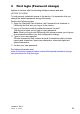
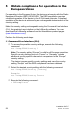


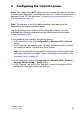


Table Of Contents
- Installation
- Contents
- Safety instructions
- General safety instructions
- Certified usage
- Installation site requirements
- Device casing
- Qualification requirements for personnel
- National and international safety regulations
- Grounding the device
- Lightning protection
- Requirements for connecting electrical wires
- Requirements for connecting the supply voltage
- ATEX directive 2014/34/EU – specific regulations for safe operation
- Relevant for use in explosion hazard areas (Hazardous Locations, Class I, Division 2):
- E marking
- CE marking
- LED or laser components
- FCC note
- Note for the use in the Japan
- Note for the use in Oman
- Recycling note
- About this manual
- Key
- 1 Description
- 1.1 General description
- 1.2 Device name and product code
- 1.3 Device view
- 1.4 Power supply
- 1.4.1 Supply voltage with the characteristic value C (24 V DC ... 48 V DC)
- 1.4.2 Supply voltage with the characteristic value K (60 V DC ... 250 V DC / 110 V AC ... 230 V AC, 50 Hz ... 60 Hz)
- 1.4.3 Supply voltage with the characteristic value P (Power supply only through PoE)
- 1.4.4 Supply voltage with the characteristic value W (24 V DC)
- 1.5 Ethernet ports
- 1.6 Connections for antennas
- 1.7 Display elements
- 1.8 Management interfaces
- 1.9 Signal contact
- 1.10 Reset button
- 2 Installation
- 3 Making basic settings
- 4 First login (Password change)
- 5 Obtain compliance for operation in the European Union
- 6 Configuring the transmit power
- 7 Configuring the transmit power for the 4.9 GHz band
- 8 Maintenance and service
- 9 Disassembly
- 10 Technical data
- 10.1 General technical data
- 10.2 Dimension drawings
- 10.3 Radio technology
- 10.4 Roaming
- 10.5 Receiving sensitivity, transmit power, and data rate of the WLAN module version EWLAN1 (Approvals 2, characteristic value M or 9)
- 10.6 Receiving sensitivity, transmit power, and data rate of the WLAN module version EWLAN1 for device variants with approval for the 4.9 GHz band (Approvals 2, characteristic value P)
- 10.7 Receiving sensitivity, transmit power, and data rate of the WLAN module version EWLAN2 for high-gain antennas (Approvals 2, characteristic value H)
- 10.8 EMC and immunity
- 10.9 Network range
- 10.10 Power consumption/power output
- 11 Scope of delivery, order numbers and accessories
- 12 Underlying technical standards
- A Further support
Installation BAT-F
Release
18
07/2020
59
7 Configuring the transmit power for the
4.9 GHz band
Note: This chapter exclusively applies to device variants with approval for
the 4.9 GHz band (Approvals 2, characteristic value P).
Note: The operator of a WLAN radio installation must adhere to the
applicable transmission threshold values.
Use the graphical user interface or the LANconfig software. You can
download the LANconfig software from the Hirschmann product pages
(www.hirschmann.com).
In the graphical user interface, proceed as follows:
Open the Configuration > Wireless LAN > General dialog.
In the “General” frame in the “Restrict to 4.9GHz operation mode” row,
choose the “Enabled” option in the drop-down list.
Note: For devices operating in the 4,9 GHz band according to
FCC 47CFR Part 90 Subpart Y the following applies:
For antennas with an antenna gain >9 dBi, the transmit power must be
reduced accordingly in the device software. For more detailed information
see the following step-by-step instructions.
Open the HiLCOS Menu Tree > Setup > Interfaces > WLAN >
Radio-Settings dialog.
In the “lfc” column, click the physical WLAN interface to which you
connect the antenna.
In the “Radio-Band” row, choose the “5GHz” option in the drop-down list.
Subtract the cable and installed overvoltage protector attenuation from
the antenna gain. If the value after subtracting the attenuation is 9dBi,
you do not need to do anything else.
If the value is >9 dBi, proceed as follows:
Calculate the difference to the maximum permitted antenna gain of 9 dBi.
Example calculation for an antenna gain of 14 dBi and an attenuation of
2dBi:
Step 1 (antenna gain minus attenuation):
14 dBi - 2 dBi = 12 dBi
As the value is >9 dBi, the difference to the maximum permitted 9 dBi
must be calculated in Step 2.
Step 2: 12 dBi - 9 dBi = 3 dBi
Enter the difference you have calculated in the “Tx-Power-Reduction”
field.