
User's Manual


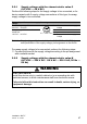


Table Of Contents
- Installation
- Contents
- Safety instructions
- General safety instructions
- Certified usage
- Installation site requirements
- Device casing
- Qualification requirements for personnel
- National and international safety regulations
- Grounding the device
- Lightning protection
- Requirements for connecting electrical wires
- Requirements for connecting the supply voltage
- ATEX directive 2014/34/EU – specific regulations for safe operation
- Relevant for use in explosion hazard areas (Hazardous Locations, Class I, Division 2):
- E marking
- CE marking
- LED or laser components
- FCC note
- Note for the use in the Japan
- Note for the use in Oman
- Recycling note
- About this manual
- Key
- 1 Description
- 1.1 General description
- 1.2 Device name and product code
- 1.3 Device view
- 1.4 Power supply
- 1.4.1 Supply voltage with the characteristic value C (24 V DC ... 48 V DC)
- 1.4.2 Supply voltage with the characteristic value K (60 V DC ... 250 V DC / 110 V AC ... 230 V AC, 50 Hz ... 60 Hz)
- 1.4.3 Supply voltage with the characteristic value P (Power supply only through PoE)
- 1.4.4 Supply voltage with the characteristic value W (24 V DC)
- 1.5 Ethernet ports
- 1.6 Connections for antennas
- 1.7 Display elements
- 1.8 Management interfaces
- 1.9 Signal contact
- 1.10 Reset button
- 2 Installation
- 3 Making basic settings
- 4 First login (Password change)
- 5 Obtain compliance for operation in the European Union
- 6 Configuring the transmit power
- 7 Configuring the transmit power for the 4.9 GHz band
- 8 Maintenance and service
- 9 Disassembly
- 10 Technical data
- 10.1 General technical data
- 10.2 Dimension drawings
- 10.3 Radio technology
- 10.4 Roaming
- 10.5 Receiving sensitivity, transmit power, and data rate of the WLAN module version EWLAN1 (Approvals 2, characteristic value M or 9)
- 10.6 Receiving sensitivity, transmit power, and data rate of the WLAN module version EWLAN1 for device variants with approval for the 4.9 GHz band (Approvals 2, characteristic value P)
- 10.7 Receiving sensitivity, transmit power, and data rate of the WLAN module version EWLAN2 for high-gain antennas (Approvals 2, characteristic value H)
- 10.8 EMC and immunity
- 10.9 Network range
- 10.10 Power consumption/power output
- 11 Scope of delivery, order numbers and accessories
- 12 Underlying technical standards
- A Further support

48
Installation BAT-F
Release
18
07/2020
Connect the wires for the supply voltage and the protective grounding
according to the pin assignment with a suitable socket.
2.5.3 Supply voltage with the characteristic value W
(24 V DC)
For every supply voltage to be connected, perform the following steps:
Connect the wires for the supply voltage according to the pin assignment
with a suitable socket.
Type of the
voltages that
can be
connected
Specification of the supply
voltage
Pin assignment on the device
DC voltage Rated voltage range DC:
60 V DC ... 250 V DC
PE Protective conductor
Voltage range DC incl.
maximum tolerances:
48 V DC ... 320 V DC
P+ Plus terminal of the
supply voltage
P- Minus terminal of the
supply voltage
AC voltage Rated voltage range AC:
110 V AC ... 230 V AC,
50 Hz ... 60 Hz
PE Protective conductor
Voltage range AC incl.
maximum tolerances:
88 V AC ... 265 V AC,
47 Hz ... 63 Hz
L Outer conductor
N Neutral conductor
Table 10: Supply voltage with characteristic value K (60 V DC ... 250 V DC /
110 V AC ... 230 V AC, 50 Hz ... 60 Hz): type and specification of the
supply voltage, pin assignment on the device
Type and specification of the
supply voltage
Pin assignment on the device
Rated voltage DC:
24 V DC
P- Minus terminal of the supply
voltage
Voltage range DC incl. maximum
tolerances:
16.8 V DC ... 32 V DC
N.C. —
N.C. —
P+ Plus terminal of the supply
voltage
Table 11: Supply voltage with characteristic value W (24 V DC): type and
specification of the supply voltage, pin assignment on the device
P-P+
PE
NL
PE
N.C.
P+P-
N.C.