
User's Manual


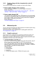


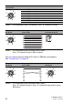
Table Of Contents
- Installation
- Contents
- Safety instructions
- General safety instructions
- Certified usage
- Installation site requirements
- Device casing
- Qualification requirements for personnel
- National and international safety regulations
- Grounding the device
- Lightning protection
- Requirements for connecting electrical wires
- Requirements for connecting the supply voltage
- ATEX directive 2014/34/EU – specific regulations for safe operation
- Relevant for use in explosion hazard areas (Hazardous Locations, Class I, Division 2):
- E marking
- CE marking
- LED or laser components
- FCC note
- Note for the use in the Japan
- Note for the use in Oman
- Recycling note
- About this manual
- Key
- 1 Description
- 1.1 General description
- 1.2 Device name and product code
- 1.3 Device view
- 1.4 Power supply
- 1.4.1 Supply voltage with the characteristic value C (24 V DC ... 48 V DC)
- 1.4.2 Supply voltage with the characteristic value K (60 V DC ... 250 V DC / 110 V AC ... 230 V AC, 50 Hz ... 60 Hz)
- 1.4.3 Supply voltage with the characteristic value P (Power supply only through PoE)
- 1.4.4 Supply voltage with the characteristic value W (24 V DC)
- 1.5 Ethernet ports
- 1.6 Connections for antennas
- 1.7 Display elements
- 1.8 Management interfaces
- 1.9 Signal contact
- 1.10 Reset button
- 2 Installation
- 3 Making basic settings
- 4 First login (Password change)
- 5 Obtain compliance for operation in the European Union
- 6 Configuring the transmit power
- 7 Configuring the transmit power for the 4.9 GHz band
- 8 Maintenance and service
- 9 Disassembly
- 10 Technical data
- 10.1 General technical data
- 10.2 Dimension drawings
- 10.3 Radio technology
- 10.4 Roaming
- 10.5 Receiving sensitivity, transmit power, and data rate of the WLAN module version EWLAN1 (Approvals 2, characteristic value M or 9)
- 10.6 Receiving sensitivity, transmit power, and data rate of the WLAN module version EWLAN1 for device variants with approval for the 4.9 GHz band (Approvals 2, characteristic value P)
- 10.7 Receiving sensitivity, transmit power, and data rate of the WLAN module version EWLAN2 for high-gain antennas (Approvals 2, characteristic value H)
- 10.8 EMC and immunity
- 10.9 Network range
- 10.10 Power consumption/power output
- 11 Scope of delivery, order numbers and accessories
- 12 Underlying technical standards
- A Further support

40
Installation BAT-F
Release
18
07/2020
You can order a terminal cable M12, 8-pin, to DB9 as an accessory.
See “Accessories” on page 82.
Pins of the M12 socket
on the device
Pin Function Description of functions
1 GND Ground
2 DTR Data terminal ready
3 TxD Transmit data
4 RxD Receive data
5 DCD Data carrier detect
6 DSR Dataset ready
7 RTS Request to send
8 CTS Clear to send
Table 4: Pin assignment of the V.24 interface, 8-pin, “A”-coded M12 socket
Pins of the M12 socket on
the device
Pin assignment for the connection
with a cable
Pins of the DB9 plug on
the external device
Table 5: Pin assignment for the connection with a cable:
8-pin, „A“-coded M12 plug to DB9 connector
Pins of the M12 socket on
the device
Pin assignment for the connection
with a cable
Pins of the M12 socket on
the device
Table 6: Pin assignment for the connection with a cable:
8-pin, “A”-coded M12 plug to 8-pin, “A”-coded M12 plug (point-to-point
WLAN line)
8
2
3
4
7
6
1
5
8
2
3
4
7
6
1
5
1
2
3
4
5
6
7
8
5
4
3
2
1
6
7
8
1
8
5
8
2
3
4
7
6
1
5
1
2
3
4
5
6
7
8
1
2
3
4
5
6
7
8
8
2
3
4
7
6
1
5