
User's Manual


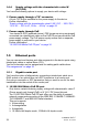


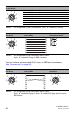
Table Of Contents
- Installation
- Contents
- Safety instructions
- General safety instructions
- Certified usage
- Installation site requirements
- Device casing
- Qualification requirements for personnel
- National and international safety regulations
- Grounding the device
- Lightning protection
- Requirements for connecting electrical wires
- Requirements for connecting the supply voltage
- ATEX directive 2014/34/EU – specific regulations for safe operation
- Relevant for use in explosion hazard areas (Hazardous Locations, Class I, Division 2):
- E marking
- CE marking
- LED or laser components
- FCC note
- Note for the use in the Japan
- Note for the use in Oman
- Recycling note
- About this manual
- Key
- 1 Description
- 1.1 General description
- 1.2 Device name and product code
- 1.3 Device view
- 1.4 Power supply
- 1.4.1 Supply voltage with the characteristic value C (24 V DC ... 48 V DC)
- 1.4.2 Supply voltage with the characteristic value K (60 V DC ... 250 V DC / 110 V AC ... 230 V AC, 50 Hz ... 60 Hz)
- 1.4.3 Supply voltage with the characteristic value P (Power supply only through PoE)
- 1.4.4 Supply voltage with the characteristic value W (24 V DC)
- 1.5 Ethernet ports
- 1.6 Connections for antennas
- 1.7 Display elements
- 1.8 Management interfaces
- 1.9 Signal contact
- 1.10 Reset button
- 2 Installation
- 3 Making basic settings
- 4 First login (Password change)
- 5 Obtain compliance for operation in the European Union
- 6 Configuring the transmit power
- 7 Configuring the transmit power for the 4.9 GHz band
- 8 Maintenance and service
- 9 Disassembly
- 10 Technical data
- 10.1 General technical data
- 10.2 Dimension drawings
- 10.3 Radio technology
- 10.4 Roaming
- 10.5 Receiving sensitivity, transmit power, and data rate of the WLAN module version EWLAN1 (Approvals 2, characteristic value M or 9)
- 10.6 Receiving sensitivity, transmit power, and data rate of the WLAN module version EWLAN1 for device variants with approval for the 4.9 GHz band (Approvals 2, characteristic value P)
- 10.7 Receiving sensitivity, transmit power, and data rate of the WLAN module version EWLAN2 for high-gain antennas (Approvals 2, characteristic value H)
- 10.8 EMC and immunity
- 10.9 Network range
- 10.10 Power consumption/power output
- 11 Scope of delivery, order numbers and accessories
- 12 Underlying technical standards
- A Further support

38
Installation BAT-F
Release
18
07/2020
Inverse flashing: the LED remains inactive for a very short time (about
10 × as long), then lights up for a much longer time (about 10 × as long).
Flickering: the LED switches on and off at irregular intervals.
Running light: coordinated glowing of several LEDs which gives the
optical impression that a light source is moving from left to right and back.
1.7.2 Device state
These LEDs provide information about conditions which affect the operation
of the whole device.
1.7.3 Port status
These LEDs provide port-related information.
P1, P2 (green/red LED) Meaning
off Connection is voltage-free.
a
a. If both connections are voltage-free, the power supply is possibly running via an active
Ethernet connection at the PoE port. The port status LEDs directly on the port show you
whether an Ethernet connection is active.
green glowing Voltage present, device is operational.
red/green flashing (slowly) Charge lock active.
b
b. Which LED displays the corresponding response depends on the configuration of the power
supply connections. P2 always performs signaling if a voltage is solely present on the
connection for supply voltage 2. In all other cases, signaling is performed by P1.
red/green flashing (quickly) Unprotected configuration as no password or the default
password is set.
a
red/off flashing (quickly) Hardware error detected.
b
red/green Running light of P1
and P2
A BAT controller WLC with an incompatible protocol is
connected.
green Running light of P1
and P2
Device is searching for a BAT controller WLC.
WLAN 1, WLAN 2
(green/red LEDs)
WLAN mode Meaning
off all No WLAN network defined or WLAN module
deactivated. WLAN module does not send any
beacons.
green glowing Access Point,
P2P
At least one WLAN network defined and WLAN
module activated. WLAN module sends beacons.
green flashing
inversely
Access Point,
P2P
Number of flashes = Number of connected WLAN
stations and P2P radio lines, then there is a break.
green flashing Access Point,
P2P
DFS scanning or another scan procedure.
green flashing Client, P2P Signal strength: The faster the LED blinks, the
better the signal and thus the connection quality.
red flashing all Hardware error detected in the WLAN module.
ETH1, ETH2 (green/yellow LED) Meaning
off No network device connected