
User's Manual


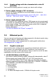


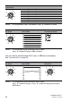
Table Of Contents
- Installation
- Contents
- Safety instructions
- General safety instructions
- Certified usage
- Installation site requirements
- Device casing
- Qualification requirements for personnel
- National and international safety regulations
- Grounding the device
- Lightning protection
- Requirements for connecting electrical wires
- Requirements for connecting the supply voltage
- ATEX directive 2014/34/EU – specific regulations for safe operation
- Relevant for use in explosion hazard areas (Hazardous Locations, Class I, Division 2):
- E marking
- CE marking
- LED or laser components
- FCC note
- Note for the use in the Japan
- Note for the use in Oman
- Recycling note
- About this manual
- Key
- 1 Description
- 1.1 General description
- 1.2 Device name and product code
- 1.3 Device view
- 1.4 Power supply
- 1.4.1 Supply voltage with the characteristic value C (24 V DC ... 48 V DC)
- 1.4.2 Supply voltage with the characteristic value K (60 V DC ... 250 V DC / 110 V AC ... 230 V AC, 50 Hz ... 60 Hz)
- 1.4.3 Supply voltage with the characteristic value P (Power supply only through PoE)
- 1.4.4 Supply voltage with the characteristic value W (24 V DC)
- 1.5 Ethernet ports
- 1.6 Connections for antennas
- 1.7 Display elements
- 1.8 Management interfaces
- 1.9 Signal contact
- 1.10 Reset button
- 2 Installation
- 3 Making basic settings
- 4 First login (Password change)
- 5 Obtain compliance for operation in the European Union
- 6 Configuring the transmit power
- 7 Configuring the transmit power for the 4.9 GHz band
- 8 Maintenance and service
- 9 Disassembly
- 10 Technical data
- 10.1 General technical data
- 10.2 Dimension drawings
- 10.3 Radio technology
- 10.4 Roaming
- 10.5 Receiving sensitivity, transmit power, and data rate of the WLAN module version EWLAN1 (Approvals 2, characteristic value M or 9)
- 10.6 Receiving sensitivity, transmit power, and data rate of the WLAN module version EWLAN1 for device variants with approval for the 4.9 GHz band (Approvals 2, characteristic value P)
- 10.7 Receiving sensitivity, transmit power, and data rate of the WLAN module version EWLAN2 for high-gain antennas (Approvals 2, characteristic value H)
- 10.8 EMC and immunity
- 10.9 Network range
- 10.10 Power consumption/power output
- 11 Scope of delivery, order numbers and accessories
- 12 Underlying technical standards
- A Further support

Installation BAT-F
Release
18
07/2020
37
1.6 Connections for antennas
The devices have 3 N sockets on each WLAN module.
The "Antenna Guide" document provides an overview of the antennas that
can be used as well as the suitable antenna accessories.
The manual is available for download on the Internet: https://
www.doc.hirschmann.com
1.7 Display elements
After the supply voltage is set up, the Software starts and initializes the
device. Afterwards, the device performs a self-test. During this process,
various LEDs light up.
These actions take less than 1 minute.
1.7.1 Meaning of the LEDs
The following terms describe the behavior of the LEDs:
Regular flashing: the LED switches on and off at regular intervals in the
specified sequence (e.g. red/off).
Brief flashing: the LED lights up very briefly, then remains inactive for a
much longer time (about 10 × as long).
LED display elements for device status and port status
LED display elements
for device status:
P1 Supply voltage connection 1
P2 Supply voltage connection 2
WLAN1 WLAN module 1
WLAN2 For device variants with 2 WLAN modules:
WLAN module 2
Note: For device variants with 1 WLAN module, this LED is
unlabeled and solely lights up after the configuration is
reset (hard reset).
LED display elements
for port status:
ETH1 Ethernet port 1
ETH2 Optional:
Ethernet port 2
Note: For device variants without this port, this LED is
unlabeled.
P1
WLAN2P2
WLAN1 ETH1
ETH2