
User's Manual


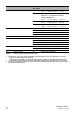
Table Of Contents
- Installation
- Contents
- Safety instructions
- General safety instructions
- Certified usage
- Installation site requirements
- Device casing
- Qualification requirements for personnel
- National and international safety regulations
- Grounding the device
- Lightning protection
- Requirements for connecting electrical wires
- Requirements for connecting the supply voltage
- ATEX directive 2014/34/EU – specific regulations for safe operation
- Relevant for use in explosion hazard areas (Hazardous Locations, Class I, Division 2):
- E marking
- CE marking
- LED or laser components
- FCC note
- Note for the use in the Japan
- Note for the use in Oman
- Recycling note
- About this manual
- Key
- 1 Description
- 1.1 General description
- 1.2 Device name and product code
- 1.3 Device view
- 1.4 Power supply
- 1.4.1 Supply voltage with the characteristic value C (24 V DC ... 48 V DC)
- 1.4.2 Supply voltage with the characteristic value K (60 V DC ... 250 V DC / 110 V AC ... 230 V AC, 50 Hz ... 60 Hz)
- 1.4.3 Supply voltage with the characteristic value P (Power supply only through PoE)
- 1.4.4 Supply voltage with the characteristic value W (24 V DC)
- 1.5 Ethernet ports
- 1.6 Connections for antennas
- 1.7 Display elements
- 1.8 Management interfaces
- 1.9 Signal contact
- 1.10 Reset button
- 2 Installation
- 3 Making basic settings
- 4 First login (Password change)
- 5 Obtain compliance for operation in the European Union
- 6 Configuring the transmit power
- 7 Configuring the transmit power for the 4.9 GHz band
- 8 Maintenance and service
- 9 Disassembly
- 10 Technical data
- 10.1 General technical data
- 10.2 Dimension drawings
- 10.3 Radio technology
- 10.4 Roaming
- 10.5 Receiving sensitivity, transmit power, and data rate of the WLAN module version EWLAN1 (Approvals 2, characteristic value M or 9)
- 10.6 Receiving sensitivity, transmit power, and data rate of the WLAN module version EWLAN1 for device variants with approval for the 4.9 GHz band (Approvals 2, characteristic value P)
- 10.7 Receiving sensitivity, transmit power, and data rate of the WLAN module version EWLAN2 for high-gain antennas (Approvals 2, characteristic value H)
- 10.8 EMC and immunity
- 10.9 Network range
- 10.10 Power consumption/power output
- 11 Scope of delivery, order numbers and accessories
- 12 Underlying technical standards
- A Further support

Installation BAT-F
Release
18
07/2020
29
14 Approvals 1 F Class I, Division 2 Groups A, B, C, D
Hazardous Locations
G ATEX Zone 2
I Substation applications (EN 61850)
K Rail applications (EN 50155)
M Motor vehicles applications (E type-
approval mark, ECE No. 10)
9 No additional approvals
15 Approvals 2 H WLAN module version for high-gain
antennas
M Motor vehicles applications (E type-
approval mark, ECE No. 10)
P Approval for the 4.9 GHz band
9 No additional approvals
16 Mounting A Indoor operator access area
a
B Indoor service access area
b
17 ... 18 Ethernet port 1 O5 Combo port – you can use these ports for
alternative purposes:
alternatively, depending on device
variant
Supply voltage with characteristic
valueC (24VDC... 48VDC)
and K (60 V DC ... 250 V DC /
110 V AC ... 230 V AC, 50 Hz ...
60 Hz):
8-pin, “X”-coded M12 socket for
10/100/1000 Mbit/s twisted pair
connections
Supply voltage with characteristic
value P (Power supply only
through PoE) and W (24 V DC):
8-pin, “X”-coded M12 socket for
10/100/1000 Mbit/s PoE PD
connections
SFP slot for 1000 Mbit/s F/O
connections
Design: IP67-V1 connector according
to IEC 61076-3-106, variant 1
19 ... 20 Ethernet port 2 T6 8-pin, “X”-coded M12 socket for 10/100/
1000 Mbit/s twisted pair connections
99 Not present
Item Characteristic Characteri
stic value
Description
Table 3: Device name and product code