
User's Manual
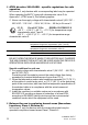

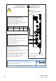


Table Of Contents
- Installation
- Contents
- Safety instructions
- General safety instructions
- Certified usage
- Installation site requirements
- Device casing
- Qualification requirements for personnel
- National and international safety regulations
- Grounding the device
- Lightning protection
- Requirements for connecting electrical wires
- Requirements for connecting the supply voltage
- ATEX directive 2014/34/EU – specific regulations for safe operation
- Relevant for use in explosion hazard areas (Hazardous Locations, Class I, Division 2):
- E marking
- CE marking
- LED or laser components
- FCC note
- Note for the use in the Japan
- Note for the use in Oman
- Recycling note
- About this manual
- Key
- 1 Description
- 1.1 General description
- 1.2 Device name and product code
- 1.3 Device view
- 1.4 Power supply
- 1.4.1 Supply voltage with the characteristic value C (24 V DC ... 48 V DC)
- 1.4.2 Supply voltage with the characteristic value K (60 V DC ... 250 V DC / 110 V AC ... 230 V AC, 50 Hz ... 60 Hz)
- 1.4.3 Supply voltage with the characteristic value P (Power supply only through PoE)
- 1.4.4 Supply voltage with the characteristic value W (24 V DC)
- 1.5 Ethernet ports
- 1.6 Connections for antennas
- 1.7 Display elements
- 1.8 Management interfaces
- 1.9 Signal contact
- 1.10 Reset button
- 2 Installation
- 3 Making basic settings
- 4 First login (Password change)
- 5 Obtain compliance for operation in the European Union
- 6 Configuring the transmit power
- 7 Configuring the transmit power for the 4.9 GHz band
- 8 Maintenance and service
- 9 Disassembly
- 10 Technical data
- 10.1 General technical data
- 10.2 Dimension drawings
- 10.3 Radio technology
- 10.4 Roaming
- 10.5 Receiving sensitivity, transmit power, and data rate of the WLAN module version EWLAN1 (Approvals 2, characteristic value M or 9)
- 10.6 Receiving sensitivity, transmit power, and data rate of the WLAN module version EWLAN1 for device variants with approval for the 4.9 GHz band (Approvals 2, characteristic value P)
- 10.7 Receiving sensitivity, transmit power, and data rate of the WLAN module version EWLAN2 for high-gain antennas (Approvals 2, characteristic value H)
- 10.8 EMC and immunity
- 10.9 Network range
- 10.10 Power consumption/power output
- 11 Scope of delivery, order numbers and accessories
- 12 Underlying technical standards
- A Further support

20
Installation BAT-F
Release
18
07/2020
FCC ID: U99EWLAN1
IC: 4019A-EWLAN1
This equipment complies with FCC and IC RSS-102 radiation exposure
limits set forth for an uncontrolled environment. Install and operate this
equipment with a minimum distance of 19.7 in (50 cm) (related to a 9 dBi
antenna) between the radiation source and your body.
The antenna used for this transmitter must not be co-located with any
other transmitters within a host device, except in accordance with FCC
multi-transmitter product procedures.
This transmitter is restricted to indoor use only within the
5.15 to 5.25 GHz band to reduce potential for harmful interference to co-
channel mobile satellite systems.
The power of the device was reduced by 6 dB on channel 149
(5745 MHz) for all modulations to be compliant to the band edge limits.
This Class B digital apparatus complies with Canadian ICES-003.
Cet appareil numérique de la classe B est conforme à la norme NMB-003
du Canada.
To reduce potential radio interference to other users, the antenna type
and its gain should be so chosen that the equivalent isotropically radiated
power (EIRP) is not more than that permitted for successful
communication.
This device has been designed to operate with the antennas listed below
in point-to-multipoint systems, and having a maximum gain of 9 dBi:
The FCC approval is valid only in conjunction with the listed antennas. If
other antennas are used, the approval expires. The responsibility lies with
the operator of the system. The required antenna impedance is 50 .
Antenna(s) for operation with this
device:
Permitted band of operation
2.4 GHz band 5.18 GHz ...
5.24 GHz band
5.745 GHz ...
5.825 GHz band
BAT-ANT-RSMA-2AGN-R
a
a. Note: When using 3 antennas type BAT-ANT-RSMA-2AGN-R, you must align each antenna
in another spatial direction (x-y-z) so that one antenna is arranged vertically to the device
and the other two antennas are arranged at right angles to each other.
Yes Yes Yes
BAT-ANT-N-3AGN-IP67 Yes Yes Yes
BAT-ANT-N-MiMoDB-5N-IP65 Yes Yes Yes
BAT-ANT-N-MiMo5-9N-IP65 No Yes Yes
BAT-ANT-N-8G-DS-IP65 Yes No No