
User's Manual
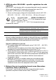

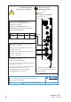


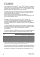
Table Of Contents
- Installation
- Contents
- Safety instructions
- General safety instructions
- Certified usage
- Installation site requirements
- Device casing
- Qualification requirements for personnel
- National and international safety regulations
- Grounding the device
- Lightning protection
- Requirements for connecting electrical wires
- Requirements for connecting the supply voltage
- ATEX directive 2014/34/EU – specific regulations for safe operation
- Relevant for use in explosion hazard areas (Hazardous Locations, Class I, Division 2):
- E marking
- CE marking
- LED or laser components
- FCC note
- Note for the use in the Japan
- Note for the use in Oman
- Recycling note
- About this manual
- Key
- 1 Description
- 1.1 General description
- 1.2 Device name and product code
- 1.3 Device view
- 1.4 Power supply
- 1.4.1 Supply voltage with the characteristic value C (24 V DC ... 48 V DC)
- 1.4.2 Supply voltage with the characteristic value K (60 V DC ... 250 V DC / 110 V AC ... 230 V AC, 50 Hz ... 60 Hz)
- 1.4.3 Supply voltage with the characteristic value P (Power supply only through PoE)
- 1.4.4 Supply voltage with the characteristic value W (24 V DC)
- 1.5 Ethernet ports
- 1.6 Connections for antennas
- 1.7 Display elements
- 1.8 Management interfaces
- 1.9 Signal contact
- 1.10 Reset button
- 2 Installation
- 3 Making basic settings
- 4 First login (Password change)
- 5 Obtain compliance for operation in the European Union
- 6 Configuring the transmit power
- 7 Configuring the transmit power for the 4.9 GHz band
- 8 Maintenance and service
- 9 Disassembly
- 10 Technical data
- 10.1 General technical data
- 10.2 Dimension drawings
- 10.3 Radio technology
- 10.4 Roaming
- 10.5 Receiving sensitivity, transmit power, and data rate of the WLAN module version EWLAN1 (Approvals 2, characteristic value M or 9)
- 10.6 Receiving sensitivity, transmit power, and data rate of the WLAN module version EWLAN1 for device variants with approval for the 4.9 GHz band (Approvals 2, characteristic value P)
- 10.7 Receiving sensitivity, transmit power, and data rate of the WLAN module version EWLAN2 for high-gain antennas (Approvals 2, characteristic value H)
- 10.8 EMC and immunity
- 10.9 Network range
- 10.10 Power consumption/power output
- 11 Scope of delivery, order numbers and accessories
- 12 Underlying technical standards
- A Further support

Installation BAT-F
Release
18
07/2020
15
Rev.: 0
page 2 of 2
For Use in Hazardous Locations Class I, Division 2 Groups A, B, C, D:
Only allowed for BAT-F model No’s. which are individually labelled
“FOR USE IN HAZARDOUS LOCATIONS”
Non-incendive field wiring circuits must be wired in accordance with the
National Electrical Code (NEC), NFPA 70 , article 501.
WARNING – EXPLOSION HAZARD – SUBSTITUTION OF ANY
COMPONENTS MAY IMPAIR SUITABILITY FOR HAZARDOUS
LOCATIONS OR EXPLOSIVE ATMOSPHERES.
WARNING – EXPLOSION HAZARD – DO NOT DISCONNECT
EQUIPMENT UNLESS POWER HAS BEEN SWITCHED OFF
OR THE AREA IS KNOWN TO BE NON-HAZARDOUS.
Notes:
The non-incendive field wiring circuit concept allows interconnection of
non-incendive field wiring apparatus and associated nonincendive field wiring
apparatus using any of the wiring methods permitted for unclassified locations
when certain parametric conditions are met.
Capacity: C
a
or C
0
≥ C
i
+ C
Cable
;
Inductivity: L
a
or L
0
≥ L
i
+ L
Cable
CONTROL DRAWING for BAT-F devices according to
Class 1, Division 2 Hazardous Locations or according to the
European Directive 2014/34/EU
Document No.: 000183360DNR